First, to clarify various signals to the LED display, LED display system block diagram shown in Figure 1.
Figure 1 LED display system block diagram
From Fig. 1, it can be analyzed that the LED display screen is composed of three parts: a data acquisition system, a control system, and a display system. The direction of the data signal is: peripheral - computer - DVI graphics card - data transmission card - data receiving card - HUB adapter board - display.
The actual situation is that the HUB adapter board is the last ring of data transmission, and all signals can be found on the HUB adapter board. The HUB adapter board is a card board that divides the signal sent by the control board into several branches, also called a distribution board. Under normal circumstances, it is determined according to the vertical number of modules of the LED electronic screen itself. Figure 2 shows the HUB adapter plate.
Figure 2 HUB adapter board
The various signals contained in the display can be clearly seen from Figure 2. The signal starts from the HUB board and is connected to the unit board or module through the cable to complete the data transmission. All signals are transmitted in parallel except that the data signal is a serial transmission. The various signal effects are now analyzed as follows.
CLK Clock Signal: A shift pulse that is supplied to the shift register. Each pulse will cause data to be shifted in or out of one bit. The data on the data port must be coordinated with the clock signal to transmit the data normally. The frequency of the data signal must be 1/2 times the frequency of the clock signal. In any case, when the clock signal is abnormal, the whole board will be displayed in a disorderly manner.
STB latch signal: When one channel of data transmission is completed, the STB latch signal is valid, the data in the shift register is latched, and the data content thereof is displayed by the driving circuit lighting LED. However, since the drive circuit is controlled by the EN enable signal, the premise of the illumination must be that the enable state is enabled. The latched signal also needs to be coordinated with the clock signal to display the complete image. In any case, when the latch signal is abnormal, the whole board will be displayed in a mess.
EN enable signal: Full screen brightness control signal, also used for display blanking. The brightness can be controlled by adjusting its duty cycle. When the enable signal is abnormal, the whole screen will appear unlit, dark or trailing.
Color Data Signal: Provides the data needed to display an image. It must be coordinated with the clock signal to transfer the data to any of the display points. Generally, the red, green and blue data signals are separated in the display. If a data signal is short-circuited to the positive or negative pole, the corresponding color will appear full or no light. When the data signal is suspended, the corresponding color is displayed. The situation is uncertain.
ABCD line signal: only exists in the dynamic scan display, ABCD is actually a binary number, A is the lowest bit, if the binary display ABCD signal control maximum range is 16 lines (0000-1111), as long as AB signal in 1/4 scan That's it, because the representation range of the AB signal is 4 lines (00-11). When an abnormality occurs in the line control signal, misalignment, highlighting, or image overlap will occur.
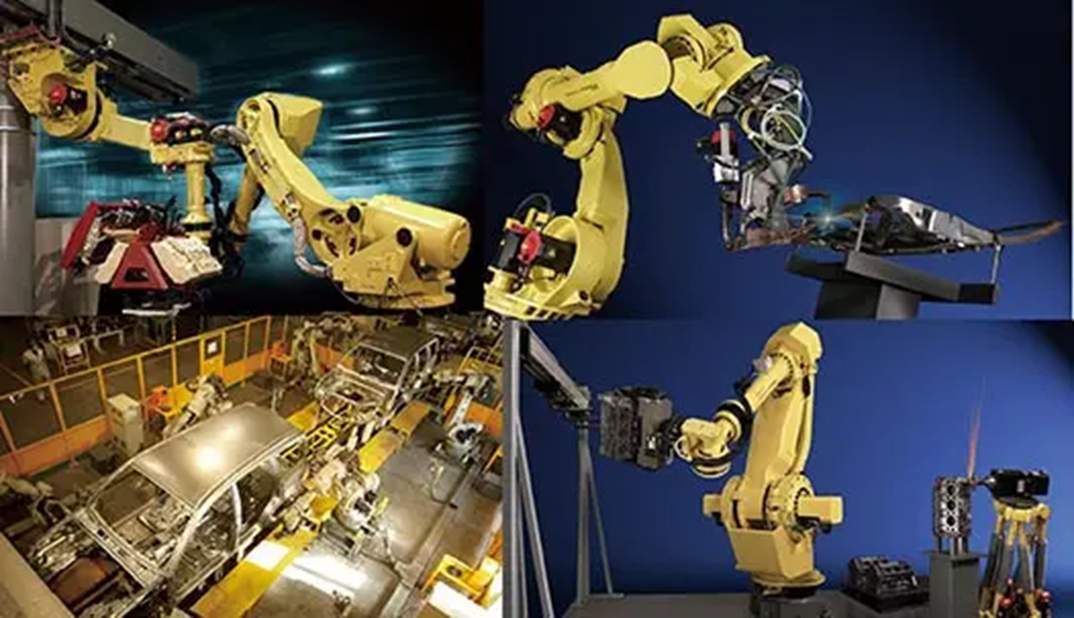
The robot Cable Assembly drag chain cable is mainly suitable for occasions with frequent movement and bending, because more common cables should have: high flexibility, oil resistance, shallow water and moisture resistance, UV resistance, excellent weather resistance, low temperature resistance, wear resistance, and can withstand heavier mechanical external forces ; The cable has faster acceleration and stronger bending resistance than ordinary flexible cables.
The robot cable assembly has the characteristics of high torsion resistance, and is cleverly routed between the curved mechanical arms, which can withstand more bending times, which greatly increases the service life of the equipment.
Artificial intelligence robotic cable assembly and industrial manipulator harnesses are mainly used in intelligent sweepers, industrial manipulators, service robots, etc. Their main features: Industrial robot wire harnesses are generally a combination of multi-plug and multi-wire harnesses, which are also combined with different electronic components. It has strong fatigue resistance, strong wear resistance, super bending resistance and high insulation level.
Kable-X has passed ISO9001 quality system certification, UL certification, ISO13485 medical quality system certification, ISO/TS16949 automotive quality system certification, etc.
We focus on customized high-end wiring harnesses in the fields of industry, medical, new energy, vehicle, and communication. Our team has Wire Harness R&D capability and more than 20 experienced wire harness engineers.
Welcome to consult.


Robotic Cable Assembly, Robotic Cable Assy, Robotic Cable Harness Assembly,New Energy Medical Cable Assemblies
Kable-X Technology (Suzhou) Co., Ltd , https://www.kable-x-tech.com
