
When the waveform is captured, many engineers think that the waveform can be very clear when the screen is 2 squares. It is not necessary to adjust the waveform to cover the screen grid. In fact, this is a misunderstanding. Today we will take a look at why we want the waveform to fill the grid of the oscilloscope screen.
The most obvious of the 2 grid display and the full grid display is that the waveform is “stretchedâ€, that is, the vertical gear position becomes smaller, and the vertical gear position directly affects the accuracy of the vertical measurement. The most important of these is the relationship between the oscilloscope's 8-bit ADC and the vertical measurement.
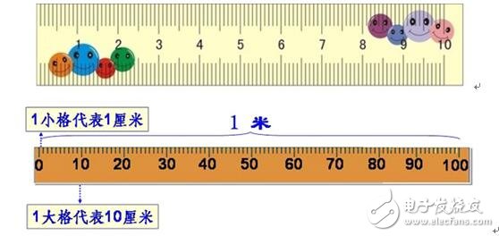
Figure 1 Ruler measurement
For example, with a 1 meter ruler and a 1.6 cm piece with a 10 cm ruler, the meter ruler may measure 2 cm, or it is difficult to estimate, and the 10 cm ruler measures 1.6 cm. The smaller the minimum unit, the more accurate the measurement, such as meter ruler, ruler, micrometer...
How does the change in the vertical gear affect the accuracy of the measurement?
1, the impact of vertical resolution on vertical measurement
A typical digital oscilloscope uses an 8-bit ADC that recombines any of the waveform values ​​with 256 0's and 1's. Assume that the oscilloscope has a full-scale vertical range of 8 cells, corresponding to a quantization level of 256. In the case where the vertical scale is 500 mV/div, the vertical accuracy is (500 mV*8) / 256 = 15.625 mV. Measuring the same signal, with a vertical gear of 50mV/div, ie (50mV*8)/256=1.5625 mV, the vertical accuracy is 1.5625 mV.
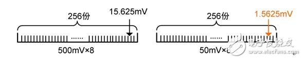
Figure 2 Measurement accuracy
In order to make the measurement as accurate as possible, the following operations can be performed:
Make the test signal amplitude as much as possible to about 6 div of the screen. For example, a sine wave with a peak-to-peak value of 7Vpp should be set to 1V/div instead of 2V/div or 5V/div. In fact, this involves a voltage resolution problem, the ZDS2024 plus oscilloscope ADC has a quantized resolution of 25LSB/div. For example, at 1V/div voltage, the voltage resolution is 1V/25=40mv, and when 10V/div, the voltage resolution is 10V/25=400mv. It can be seen that at 1V/div, the measured value has a higher resolution and the measured value is more accurate.
2, example application
Use the signal generator to generate a sine wave signal with a peak-to-peak value of 6Vpp. Input the ZDS2024 Plus oscilloscope for measurement. After the waveform is captured, the peak-to-peak measurement is performed on the waveform, as shown in Figure 3 and Figure 4 below.
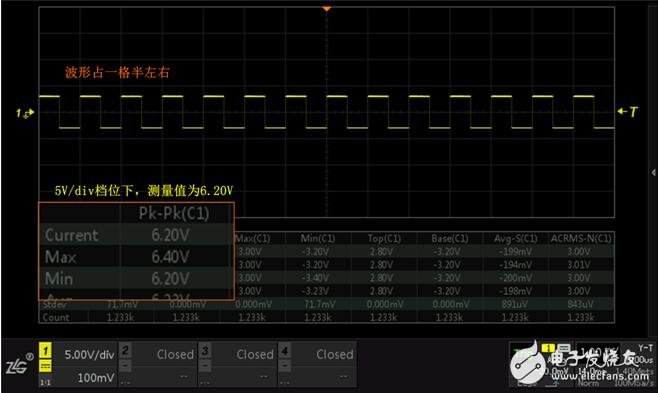
Figure 3 5V/div gear 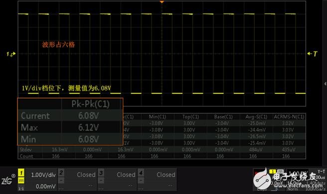
Figure 4 1V/div gear
In the 1V/div position, the quantization resolution is 40mv, and the 5V/div position has a quantization resolution of 200mv, which may differ by 1~2 resolutions during measurement.
When the waveform occupies 1.5 grids of the screen, the measured peak-to-peak value is 6.20V, which differs by 1 resolution, and the peak-to-peak error relative to 6V is 3.3%.
When the waveform occupies 6 grids of the screen, the measured peak-to-peak value is 6.08V, which differs by 2 resolutions, and the peak-to-peak error relative to 6V is 1.3%.
Expansion: Is the measured value of 6.12V and 6.20V within the error tolerance?
The allowable range of vertical measurement error is shown in Table 1.
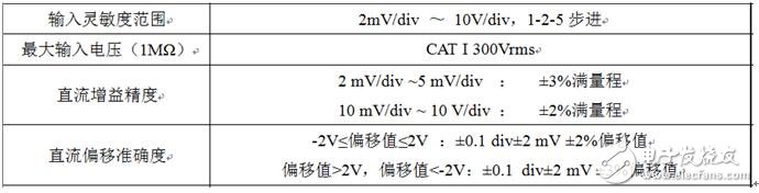
Table 1 List of vertical measurement error ranges
(1) The vertical gear is 1V/div, and the measured value is 6.08V.
Since the vertical offset is 0 in the above measurement, the DC offset accuracy is ±0.1 div±2mv±2%*0=12mv; the DC gain accuracy is 2%*(1V*8)=0.16V, so at 1V/ The allowable error in the div gear is 0.172V. 0.172V>0.08V, so the measured value is within the error tolerance.
(2) The vertical gear is 5V/div, and the measured value is 6.20V.
Since the vertical offset is 0 in the above measurement, the DC offset accuracy is ±0.1 div±2mv±2%*0=12mv; the DC gain accuracy is 2%*(5V*8)=0.8V, so at 5V/ The allowable error in the div gear is 0.812V. 0.812V>0.2V, so the measured value is within the error tolerance.
In summary, when the waveform is as close as possible to the screen, that is, the smaller the vertical scale, the higher the vertical resolution, and the more accurate the measurement, you can try it.
2.5mm Wire To Board Connector
Dongguan City Yuanyue Electronics Co.Ltd , https://www.yuanyueconnector.com