
The Hall current sensor is based on the magnetic balance Hall principle. According to the Hall effect principle, a current Ic is input from the control current end of the Hall element, and a magnetic field having a magnetic field strength B is applied in the normal direction of the Hall element plane. Then, perpendicular to the direction of the current and the magnetic field (ie between the Hall outputs), a potential VH is generated, which is called the Hall potential, and its magnitude is proportional to the control current I. The product of the magnetic field strength B. In the formula: K is the Hall coefficient, which is determined by the material of the Hall element; To control the current; B is the magnetic field strength; VH is the Hall potential.
The Hall device is a magnetoelectric conversion device made of a semiconductor material. If the control current IC is applied to the input terminal, when a magnetic field B passes through the magnetic sensitive surface of the device, a Hall potential VH appears at the output. The magnitude of the Hall potential VH is proportional to the product of the control current IC and the magnetic flux density B, that is, VH = KHICBsin Θ. The Hall current sensor is fabricated according to the Hall effect principle and applies Ampere's law to generate a magnetic field proportional to the current around the current carrying conductor, and the Hall device is used to measure this magnetic field. Therefore, non-contact measurement of current is made possible. The magnitude of the current carrying conductor current is measured indirectly by measuring the magnitude of the Hall potential. Therefore, the current sensor is subjected to an electro-magnetic-electrical insulation isolation conversion.
working principle1. Direct-release (open loop) current sensor (CS series)
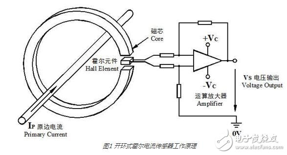
When the primary current IP flows through a long wire, a magnetic field is generated around the wire. The magnitude of this magnetic field is proportional to the current flowing through the wire. The generated magnetic field is concentrated in the magnetic ring and passes through the magnetic ring air gap. The Hall element measures and amplifies the output, and its output voltage VS accurately reflects the primary current IP. The typical rated output is calibrated to 4V.
2, magnetic balance (closed loop) current sensor (CSM series)
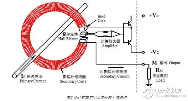
The magnetic balance type current sensor is also called a compensation type sensor, that is, the magnetic field generated by the primary side current Ip at the collecting magnetic ring is compensated by the magnetic field generated by a secondary coil current, and the compensation current Is accurately reflects the primary side current Ip, thereby The Hall device is placed in an operating state that detects zero flux.
The specific working process is: when a current flows through the main circuit, the magnetic field generated on the wire is collected by the magnetic ring and sensed on the Hall device, and the generated signal output is used to drive the power tube and turn it on, thereby obtaining a compensation. Current Is. This current then generates a magnetic field through the multi-turn winding, which is exactly opposite to the magnetic field generated by the current being measured, thus compensating for the original magnetic field, causing the output of the Hall device to gradually decrease. When the magnetic field generated by multiplying Ip and the number of turns is equal, Is no longer increases. At this time, the Hall device functions to indicate zero magnetic flux, and Ip can be tested by Is at this time. When Ip changes, the balance is destroyed, and the Hall device has a signal output, that is, the above process is repeated to reach equilibrium again. Any change in the measured current will destroy this balance. Once the magnetic field is out of balance, the Hall device has a signal output. Immediately after power amplification, a corresponding current flows through the secondary winding to compensate for the unbalanced magnetic field. From the imbalance of the magnetic field to the rebalancing, the time required is theoretically less than 1 μs, which is a process of dynamic equilibrium. Therefore, from a macro perspective, the secondary compensation current ampere is equal to the number of ampere-turns of the primary measured current at any time.
3. Hall voltage (closed loop) sensor (VSM series)
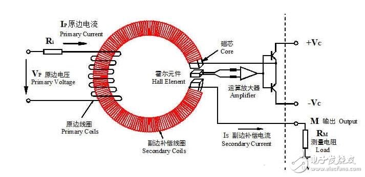
The Hall voltage sensor works like a closed-loop current sensor and works in a magnetically balanced manner. The primary voltage VP generates a current through the current limiting resistor Ri, and flows through the primary coil to generate a magnetic field, which is collected in the magnetic ring, and the compensation current IS controlled by the output signal of the Hall element in the magnetic ring air gap flows through the magnetic field generated by the secondary coil. The compensation is performed, and the compensation current IS accurately reflects the primary voltage VP.
4, AC current sensor (A-CS series)
The AC current sensor mainly measures the AC signal current. The AC signal induced by the Hall is converted into a standard DC signal output of 0 to 4V, 0 to 20 mA (or 4 to 20 mA) through AC-DC and other conversions for use in various systems.
work processThe open-loop Hall current sensor uses the Hall direct-release principle, and the closed-loop Hall current sensor uses the magnetic balance principle. Therefore, the closed loop is much better in response time and accuracy than the open loop. Both open loop and closed loop can monitor AC power. Generally, open loop is suitable for large current monitoring, and closed loop is suitable for small current monitoring.
The working process of the open-loop Hall sensor:
When the primary current (Ip) passes through a wire, a magnetic field is generated around the wire. The magnitude of this magnetic field is proportional to the current flowing through the wire. It can be sensed by the core to the Hall device and There is a signal output. This signal is directly amplified by the signal amplifier, and the signal output by the Hall device accurately reflects the output of the primary current.
Advantages: small package size, wide measuring range, light weight, low power loss, no insertion loss
The working process of the closed-loop Hall current sensor:
When the magnetic flux generated by the primary current IP is concentrated in the magnetic circuit through the magnetic core, the Hall device is fixed in the air gap to detect the magnetic flux, and the multi-turn coil wound around the magnetic core outputs a reverse compensation current for canceling The magnetic flux generated by the primary current (IP) keeps the magnetic flux in the magnetic circuit always at zero. The secondary side compensation current generated by the Hall device and the auxiliary circuit accurately reflects the magnitude of the primary current. After special circuit processing, the output of the sensor can output a current change that accurately reflects the primary current.
Hall sensor magnetic saturation problemMany Hall current sensor manufacturers also promote non-magnetic saturation as an important advantage of Hall current sensors in their technical data. The Hall current sensor does not suffer from magnetic saturation. It is one of the main advantages that Hall current sensors have been widely recognized since their application.
Is this the case?
In fact, the Hall current sensor contains a non-linear core, which has determined that the Hall current sensor will be magnetically saturated under certain conditions!
1. Magnetic saturation problem of open-loop Hall current sensor
The following figure shows a typical magnetization curve for all highly magnetically permeable materials:
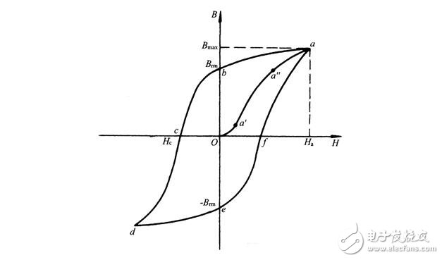
Figure 1 Magnetization curve of the Hall current sensor core
In the figure, Oa' is the initial nonlinear segment, a'a'' is a linear segment, and a''a is a saturated region. In order to obtain better measurement results, whether it is an open-loop Hall current sensor or an electromagnetic transformer, a segment with better linearity in the magnetization curve is used as a working interval. In other words, magnetic saturation occurs as long as the magnetic induction exceeds a certain range of the linear region.
Compared with electromagnetic transformers, open-loop Hall current sensors have only one magnetic saturation cause, that is, the primary current is large enough.
It does not cause magnetic saturation due to low current frequency, which is the advantage of the Hall current sensor and the magnetic saturation of the open-loop Hall current sensor.
In contrast, electromagnetic transformers also have the advantage that the secondary load is small enough that even if there is more overload, magnetic saturation will not occur.
2. Magnetic saturation problem of closed-loop Hall current sensor
The open-loop Hall current sensor magnetic saturation problem is simpler. In contrast, the closed-loop Hall current sensor magnetic saturation problem seems incomprehensible because the closed-loop Hall current sensor works normally, the magnetic flux in the core is zero. Under zero flux, it will not naturally saturate.
However, this can only be under normal working conditions!
In fact, even magnetic saturation problems of electromagnetic current transformers or open-loop Hall current sensors occur under abnormal operating conditions such as overload, low frequency, and excessive load. Under normal working conditions, they will not occur. Magnetic saturation!
From the working principle of the closed-loop Hall current sensor, the zero flux is established on the premise that the magnetic field generated by the secondary compensation winding can cancel the magnetic field generated by the primary conductor. So, can the zero-flux be maintained when the closed-loop Hall current sensor is under any circumstances?
Obviously not!
A. When the sensor is not powered, the secondary compensation winding does not generate current. At this time, the closed-loop Hall current sensor is equivalent to an open-loop Hall current sensor, and magnetic saturation occurs as long as the primary current is large enough.
B. Normal power supply, the primary current is too large. This is because the current that can be generated by the secondary compensation winding is limited. When the primary side current generates a larger magnetic field than the secondary side compensation winding can generate, the magnetic balance is broken, and the magnetic core passes through the magnetic field. When the current continues to increase, the magnetic field in the core also increases, and when the primary current is large enough, the closed-loop Hall current sensor enters the magnetic saturation state!
Compared with electromagnetic current transformers and open-loop Hall current sensors, the magnetic saturation phenomenon of closed-loop Hall current sensors is not easy to occur, but it does not mean that it will not occur. Magnetic saturation occurs due to improper use or long-term overload.
Dongguan Yangyue Metal Technology Co., Ltd , https://www.yyconnector.com