
Cree XLamp® High Power Devices Latest Application Guidelines and Points to Watch Updates
——XB-D LED and XT-E LED optical design
Cree XLamp ® XB-D LEDs and XT-E LEDs are based on Cree's latest SC3 technology platform. At the heart of Cree SC3 technology is a new generation of Direct Attach (DA) silicon chip with higher light and light efficiency and better reliability. While XLamp ® XB-D LEDs and XT-E LEDs offer higher performance, special DA chip structures present challenges for optical design. This article describes these challenges and provides a means to effectively overcome them.
First, the DA chip
As shown in Figure 2, the silicon carbide substrate produces fewer dislocations than the sapphire substrate. Each dislocation creates a tiny black dot on the surface of the chip. Fewer dislocations mean fewer black dots, brighter, higher lumen output, ie higher efficiency (lm/w). These advantages combined with the DA chip have a 5-10% improvement in light efficiency compared to sapphire substrates. Another advantage is that there are fewer epitaxial defects and the LEDs produced are more reliable. The DA chip structure therefore provides higher light output, robustness, reliability and manufacturability.
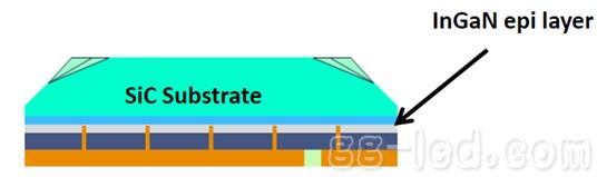
Figure 1 DA chip side view 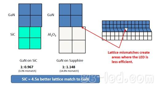
Figure 2 lattice mismatch comparison
Second, XLamp® XB-D LED and XT-E LED optical model
Cree XLamp ® XB-D and XT-E white LEDs are based on DA chips, and their optical models have some special optical properties that are distributed in a Lambertian light pattern. As seen from the schematic diagram 3 of the DA chip, in order to maximize the light output, cutting at the oblique side of the top surface of the chip poses a challenge to the secondary optical design of the LED. Due to the special cutting of the DA chip, the phosphor is deposited on the beveled cutting surface above the SiC.
For the XP series products using the EZ chip, blue light and yellow light are emitted from almost the same side. For products using the DA chip, similar to the small-sized remote phosphor structure, blue light is emitted from the InGaN epitaxial layer, and yellow light is emitted from the beveled cutting surface of the top surface of the DA chip. When designing a small angle of secondary optics, the light intensity is There may be some unevenness in the color distribution. Figures 4 and 5 show how light is produced from XLamp ® XP LEDs (EZ chips) and XB-D LEDs, XT-E LEDs (DA chips).
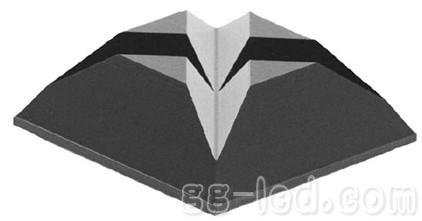
Figure 3 Schematic diagram of the DA chip 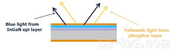
Figure 4 Schematic diagram of the EZ chip emitting light 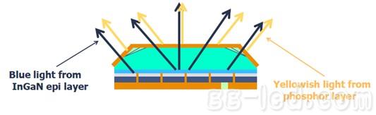
Figure 5 Schematic diagram of the light emitted by the DA chip
In order to improve the light output, there is a bevel cut on the top surface of the DA chip, which results in inconsistent phosphor thickness on the chip. Figure 6 is a near-field diagram of the XT-E LED when it is lit, paying attention to the yellow cross at the center of the figure, which indicates a thicker phosphor layer on the cross.
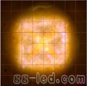
Figure 6 Near-field diagram of DA chip white LED
Third, LED secondary optical foundation
If the light distribution of the LED does not meet the specific application requirements, it is necessary to use secondary optics to change the light distribution of the LED so that the light distribution of the finished lamp meets the requirements. Secondary optics can also be used to improve color and light distribution uniformity in the target area. LED secondary optics are classified as follows: 1. Reflector, reflector 2. Lens 3. Combine lenses and reflectors, such as total reflection lenses (TIR) ​​4. Diffuser. Each optical system controls light in different ways, with different manufacturing techniques and prices. The main functions of LED secondary optics:
1) Collimation: Make most of the light most likely to shine on the target, such as a flashlight or a spotlight.
2) Diffusion: Let light spread or hide at a larger angle, blurring LED light sources, such as linear lamps or LED bulbs.
3) Illumination: illuminate light on a specific area without illuminating other areas, such as street lights or area lights.
Parabolic reflectors are very effective in collimating light and are easier to manufacture and less expensive than conventional lenses. However, the reflector has only one surface control beam, and many of the light emitted from the light source is directly emitted without being reflected by the reflective surface. The light reflected by the reflective surface is controlled and collimated, and the light that is not reflected by the reflective surface is not controlled. These lights are called spilled light.
Conversely, conventional lenses provide good control of the light at the center of the beam, but due to lens size issues, it is not possible to control light at large angles. TIR lenses are secondary optics that combine the advantages of reflectors and conventional lenses:
1) It can control both direct and reflected light 2) Make the light pass at least 2 faces before leaving the system 3) Even if the lens size is small, it will be very effective 4) Relatively high reflective glass price
As shown in Figure 7, the TIR lens comprises a total reflection (TIR) ​​face and a refractive lens. The refractive lens controls the light in the middle of the LED beam, and the TIR surface controls the light at a large angle.
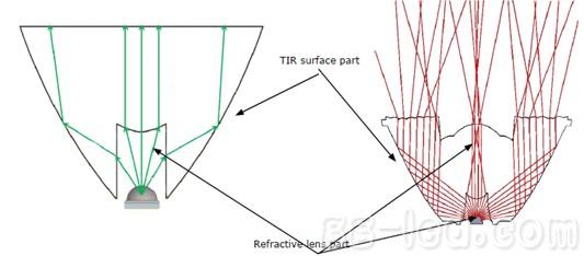
Figure 7 TIR lens
As mentioned earlier, the XLamp ® XB-D LED and XT-E LED use a DA chip, which makes the color uneven at small angles. For TIR lenses, the methods for mixing colors are:
1. The top surface of the lens is frosted or the microlens is added, as shown in Figures 8 and 9. If the added microstructure is too much, the angle of the light will be too large, and too much light will be lost. Conversely, too little color mixing will be uneven.
Figure 8 frosted surface (provided by Ledil) 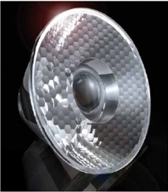
Figure 9 Microstructure (provided by Gaggione)
2. Add a diffusion structure to the refractive lens, as shown in Figure 10.
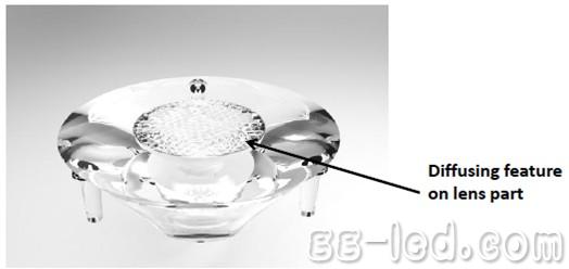
Figure 10 diffusion structure (provided by Illumination Machines)
3. The TIR surface adds a diffusion structure as shown in FIG.
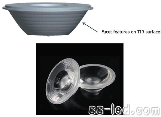
Figure 11 Diffusion structure on the TIR surface (provided by Ledlink)
The company adheres to the management policy of "seeking truth and dedication" and a strict quality assurance system. In the new century, we will follow the tenet of "innovation, progress and rigor" and a forge ahead enterprise with "excellent quality and excellence". Spirit, the supreme product, add wings to your enterprise take off. Carefully do a good job of each product, the highest quality, and integrate a dedicated attitude, dedicated spirit, skilled practice, and good reputation into the details of the service.
High Voltage Connector,High Voltage Terminal Wire Connectors,High Voltage Terminal Connectors,High Voltage Terminal Connector Terminal
Sichuan Xinlian electronic science and technology Company , https://www.sztmlch.com