
In the design process, the transmitter uses the S8050 amplifier, which is a power amplifier that amplifies its audio signal. The receiving part uses a common low-power audio amplifier D2822A, which forms the core of the infrared communication device. The device has almost no distortion in speech transmission, the transmission distance meets the requirements, and the operation is simple. When adding a relay forwarding point, changing the direction of 90 degrees, the effect is good.
1. Overall design of the program
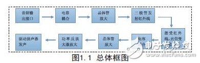
1.1 System overall design block diagram
The earphone is composed of a transmitting module and a receiving module. Transmitter module: mainly includes basic circuit and infrared light-emitting diode, which is mainly driven by 5V voltage, and the audio signal is driven by the basic circuit to drive the infrared light-emitting diode to emit the signal. Receiver module: mainly includes S8050 power amplifier and its surrounding auxiliary components. It mainly transmits the received signal through D2822A power under the driving of 5V voltage, and then drives the speaker to emit sound, so that the listener can hear the transmitter. music.
The overall principle block diagram of the system is shown in Figure 1.1.
1.2 unit circuit design
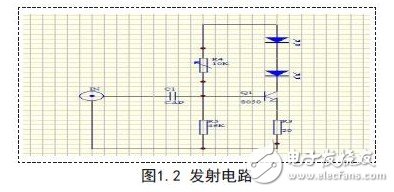
1.2.1 Transmitting part of the circuit
The sound signal is drawn from the audio output socket of the MP3 or signal generator. The audio signal output by MP3 is coupled to VT1 S8050 through capacitor C1 for one-stage amplification to drive infrared light-emitting diodes. VD1 and VD2 emit light, and the change of sound signal causes changes in the luminous intensity of VD1 and VD2, that is, the luminous intensity of VD1 and VD2 is affected by sound. modulation. The DC 5V voltage flows through the resistor R4 to VT1, and then supplies the operating voltage, amplifies the audio signal to drive the VD1 and VD2 to emit light, and transmits the signal.
The transmitting circuit is shown in Figure 1.2.
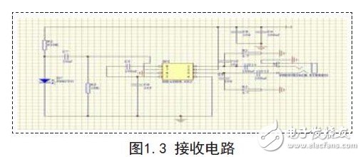
1.2.2 Receiving part of the circuit
The receiving part of the circuit uses a piece of audio amplification integrated circuit D2822A for power amplification. There is an infrared receiver tube. When the infrared light modulated by the audio signal reaches the surface of the infrared receiving tube, the receiving tube converts the received sound-modulated infrared light signal into an electrical signal, that is, generates an electrical signal having the same change rule as the audio signal at both ends of the receiving tube. The signal is coupled via C7 to power amplification to drive the speaker to sound.
The receiving circuit is shown in Figure 1.3.
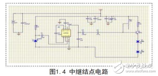
1.2.3 relay node circuit
In the design of the relay node circuit, the transmitting circuit and the receiving circuit are integrated. The light-emitting diode and the photodiode have a vertical relationship, and it is good to change the communication direction by 90 degrees, and the distance can be extended to communicate.
The circuit diagram is shown in Figure 1.4.
2. System testing
Analysis of the test plan of the circuit:
(1) When inputting 800HZ tone signal at the transmitting end, test the effective value of the voltage outputted by the receiving end on the 8 ohm resistive load;
(2) When inputting 800HZ tone signal at the transmitting end, reduce the input signal of the transmitting end to 0V (that is, block the propagation path of infrared rays), and measure the noise voltage at the output end with the low frequency millivoltmeter.
3. Conclusion
Due to the reasonable design of the system architecture, the functional circuit is better, the communication performance is excellent and stable, and the basic requirements of the requirements of the problem and some of the requirements are well met. After testing and analysis, the system can realize: 1 transmission distance up to two meters, the restored audio signal has no obvious distortion; 2 when the single audio signal is input, the effective value of the output voltage is greater than 0.4V, the noise voltage is less than 0.1V; Indicates the presence or absence of the signal; 4 can achieve relay forwarding, the communication direction changes by 90 degrees, and the signal can continue to be transmitted without significant distortion.
   Want to understand the use of TDA2822M integrated op amp and peripheral circuits to form the transmitting and receiving circuits of the infrared light-emitting tube as a communication device design, you can refer to the following article:
Design scheme based on infrared optical communication circuit
In addition, attach the 2013 National College Student Electronic Competition Test Questions Group F Topic: Design of Infrared Optical Communication Devices
2013-F-infrared optical communication device
Electronic Design Competition--Infrared Optical Communication Device Design Report
The main function of the MPPT Solar Controller is to realize maximum power point tracking (MPPT) in the solar power generation system to improve the energy utilization efficiency of solar panels. It is an advanced charge controller that can adjust the output voltage and current of the Solar Panel in real-time to keep the solar panel operating at the maximum power output point.
Main effect:
Maximum power point tracking: MPPT Solar Controller can accurately calculate the maximum power output point of the solar panel by monitoring the voltage and current of the solar panel in real-time and according to the characteristics of the solar panel. It then adjusts the panel's output voltage and current to keep it operating at its maximum power output point, maximizing the solar panel's energy conversion efficiency.
High energy utilization rate: MPPT Solar Controller's maximum power point tracking function can ensure that the solar panel is always operating in the best working condition, making full use of solar energy, thereby improving the energy utilization rate of the photovoltaic power generation system.
Charge control: In addition to achieving maximum power point tracking, MPPT Solar Controller also has a charge control function to protect the battery from overcharge and over-discharge damage.
Differences from other charge controllers:
Maximum power point tracking function: MPPT Solar Controller is a charge controller specially used in solar power generation systems. The biggest difference is that it has a maximum power point tracking function, which is used to improve the energy conversion efficiency of solar panels. Other charge controllers may not have this unique feature.
Energy efficiency: MPPT Solar Controller can improve the energy efficiency of solar panels through maximum power point tracking technology. Other charge controllers may only be able to charge in a fixed manner and cannot achieve maximum power point tracking.
Application scenarios: MPPT Solar Controller is mainly used in solar power generation systems, while other charge controllers may be suitable for different types of energy generation systems, such as wind power, hydropower, etc.
Overall, the main role of the MPPT Solar Controller is to achieve maximum power point tracking, improve the energy conversion efficiency of the solar panel, and protect the battery from overcharge and over-discharge damage. Compared with other charge controllers, it has unique advantages in energy utilization efficiency and maximum power point tracking and is suitable for applications in solar power generation systems.
10 amp mppt solar charge controller, solar charge controller 10 amp, 36v mppt solar charge controller, dc dc mppt charger, lithium ion solar charge controller
Ningbo Autrends International Trade Co., Ltd. , https://www.china-energystorage.com