Lightning protection circuits are very common application circuits on industrial circuit boards. Let us find out today.
Guangzhou Zhiyuan Electronics Co., Ltd.'s environmental power monitoring system has lightning protection design for all ports, including 220V AC power supply lightning protection design, Ethernet lightning protection, DI input port lightning protection, AI input port protection Lightning protection, RS232/RS485 lightning protection, these lightning protection circuits will be analyzed one by one.
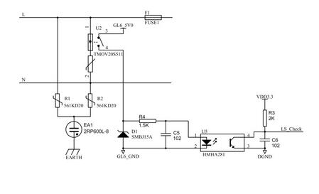
1.1.1 220V AC power supply lightning protection Environmental power monitoring system power supply is powered by 220V AC power supply, the lightning protection circuit used in the front end is shown in Figure 1.

Figure 1 220V AC power supply lightning protection circuit
Due to the use of composite symmetrical circuit and common mode, differential mode full protection, L, N can be connected casually and safely. Even if the varistor is disconnected from the circuit after a short-circuit failure, it generally does not cause a fire. According to the actual experience U2 is most vulnerable to lightning damage. Due to the aging of the varistor itself or the multiple impacts of temporary overvoltage, the leakage current of the varistor increases rapidly and the short circuit fails. The varistor short-circuit failure will cause short-circuit faults in the entire power supply line, and cause serious accidents such as fire and explosion that threaten the safety of people and property. This circuit adopts the metal zinc oxide varistor U2, so it can effectively avoid the safety hazards such as fires caused by the short-circuit failure of the traditional zinc oxide varistor. At the same time, if the isolated fuse is blown at the same time due to the lightning strike, the host CPU can detect the corresponding signal at the LS_Check end, thereby functioning as a lightning damage alarm.
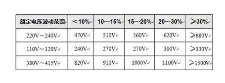
Table 1 varistor value selection list

The varistor voltage value of the varistor can be selected according to Table 1. The varistor voltage value can be appropriately selected to be higher, which is safer, more durable, and has a lower failure rate, but the residual voltage is slightly higher. Then select the external dimensions and package form according to the requirements of the current capacity, or use several varistors in parallel. Note that parallel connections with similar varistor voltage values ​​should be selected. Each varistor must be connected in series with a temperature fuse to extend the service life. And ensure safety.
The flow capacity of the ceramic gas discharge tube is selected according to the required flow capacity, and the DC breakdown voltage is 470V to 600V. When the required flow capacity is ≤ 3KA, it can be replaced with a glass discharge tube.
Both the varistor and the gas discharge tube must calculate the flow capacity according to the derating value of more than 10 times of impact (the varistor is about one-third of the impulse flow capacity, and the gas discharge tube is about half of the maximum flow capacity). ).
1.1.2 Ethernet lightning protection With the application of Ethernet technology in base station and computer room monitoring, there are more and more collection devices with network ports. Most of the previous network devices were used in the computer room and building, the computer room and the building. The lightning protection measures are very sufficient, so the previous equipment with network ports basically did not consider the lightning protection problem. At most, some transient suppression diodes (TVS tubes) were installed at the network port to prevent surges, and the protection index was very low (differential mode). 500V, common mode 1000V), when the device is used in the base station, due to the above reasons, a large number of network acquisition devices are damaged in the base station due to lightning strikes.
Faced with this problem, the user's processing strategy is to add a signal lightning protector to the network port to improve the lightning protection performance of the device. However, the addition of the lightning protection device has a lot of inconveniences. For example, it is necessary to re-do the direct connection line between the device and the lightning protection device, so that the connection point is increased from the original one to three, and the failure rate is also increased by three times. At the same time, the network port transmits 10M/100M high-speed signals, and the distributed capacitance of the external lightning protection device is large, which has an impact on the transmission of the network signal. This method is to improve the lightning protection effect of the device by sacrificing the transmission distance and speed.
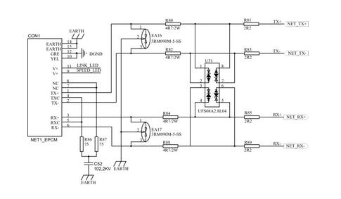
In the environmental power monitoring system, a lightning protection effect is provided, which prevents the network equipment from being damaged by lightning strikes, does not affect the network transmission performance, and can ensure the network transmission distance and speed of the monitoring collection device network port lightning protection. Circuit. See Figure 2 for details.

Figure 2 Ethernet port lightning protection circuit
In the lightning protection circuit of the network port as shown in FIG. 2, a two-stage protection circuit composed of a discharge tube and a bidirectional transient voltage bleeder circuit is added between the network transformer and the network port socket, which greatly enhances the difference of the network port. Mode protection. The first current limiting resistors R80, R82, R84, R88 and the gas discharge tubes EA16 and EA17 form a first-level protection circuit for the first-level protection of the surge voltage of the lightning strike, with the bleeder lightning transient overcurrent and current limiting Voltage action. The primary protection circuit can generate a large bleeder current (3KA), and most of the intrusion energy is vented through the ground. On this basis, the bidirectional transient voltage bleeder circuit composed of U31 and R81, R83, R85 and R89 constitutes a secondary protection circuit, which performs bidirectional residual voltage absorption on the differential signal and performs the second stage of the surge voltage of the lightning strike. Protection, the remaining energy is discharged through the bidirectional transient voltage bleeder circuit, and the energy to the network transformer is very small. Under the action of the two-stage protection circuit, the circuit has a good lightning protection effect and can prevent damage caused by lightning strikes on network equipment.
In the primary protection circuit, the parasitic capacitance of the gas discharge tube is very small; in the secondary protection circuit, a transient voltage bleed integrated IC composed of a diode, a transient voltage suppression diode, and a diode series is used, which greatly reduces the The TVS tube has a large junction capacitance in the secondary protection circuit. Therefore, the lightning protection circuit of the network port does not affect the network transmission performance, and can ensure the original network transmission distance and transmission speed, the network transmission distance and the network port waveform can meet the specification requirements, and have a good lightning protection effect.
In the lightning protection circuit of the network port as shown in FIG. 2, in order to select the device, in order not to affect the network waveform and transmission performance, the resistance of the first current limiting resistor is an ohmic level, and R80, R82, and R84 are used in the circuit. The resistance value of R88 is 4.7Ω. In order to protect the network transformer without affecting the network transmission performance, the resistance of the second current limiting resistor (R81, R83, R85, R89) can be between 0Ω and 10Ω, preferably between 2Ω and 3Ω, in this circuit. The resistance values ​​of R81, R83, R85, and R89 are 2.2Ω. In order to reduce the size of the circuit and reduce the influence of distributed capacitance, this circuit uses a transient voltage bleeder integrated IC (UFS08A2.8L04) consisting of a diode, a transient voltage suppression diode, and a series of diodes, since UFS08A2.8L04 contains 4 A transient voltage bleed branch consisting of a first diode, a transient unidirectional voltage suppression diode, and a second diode in series, so that each network port transmits a lightning protection circuit and a signal line of the signal line. The lightning protection circuit can share a UFS08A2.8L04 chip, which greatly reduces the influence of the circuit volume and distributed capacitance.
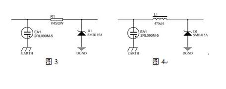
1.1.3 AI/DI input port lightning protection In the base station environment, since the AI/DI input port is connected to the sensor through a long-distance cable, the AI/DI port also has lightning protection (mainly inductive lightning). In the RMS-500 system, we use a two-stage protection circuit consisting of a gas discharge tube and a TVS tube, as shown in Figure 3 and Figure 4.

In Figure 3 and Figure 4, we can see the difference between the AI ​​lightning protection circuit and the DI lightning protection circuit. In the DI lightning protection circuit, we use the power resistor R1 (7.5Ω/2W), R1 should meet R1≥(U1 -U2) /I1, where U1 is the measured impact breakdown voltage of the air discharge tube, U2 is the highest clamp voltage of the TVS tube, and I1 is obtained by the TVS device manual 8/20us inrush current. Maximum flow rate. In the AI ​​lightning protection circuit, since the current and voltage of 4~20mA need to be measured, we use the inductor L1 within the accuracy range without using the resistor. L1 should satisfy L1≥(U1 -U2) × (T2 -T1) / ( I1 /2), the calculation method of the inductance L1 is: based on the 8/20us inrush current, the residual voltage value U1 of the varistor under the designed current capacity is measured, and the TVS device manual is obtained to obtain 8/20us surge current. The maximum through flow I1 of the TVS tube and the highest clamp voltage U2 of the TVS tube, the apparent wave head time of the 8/20us inrush current T1=8us, depending on the half-peak time T 2=20us.
Half-cell Monocrystalline Solar Panel
Jiangsu Stark New Energy Co.,Ltd , https://www.stark-newenergy.com
