
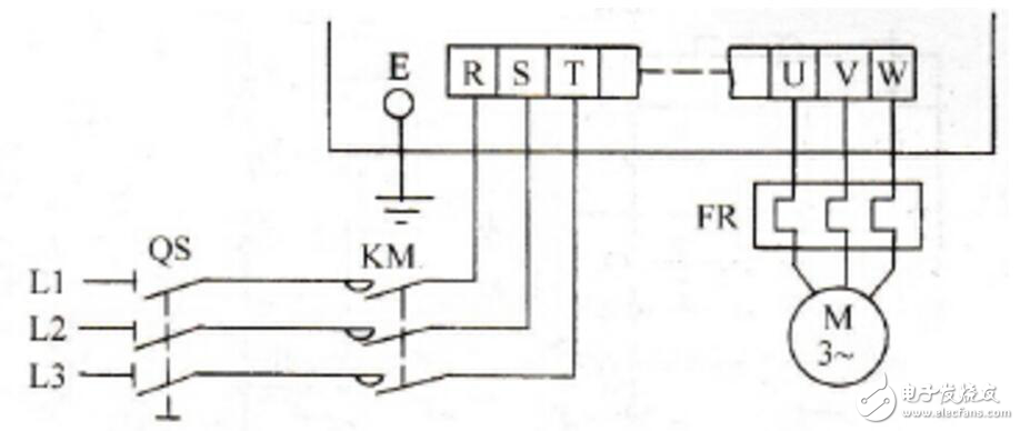
1) The main circuit power terminals R, S, T are connected to the power supply via a contactor and an air circuit breaker, regardless of the phase sequence.
2) When the protection function of the inverter is activated, the normally closed contact of the relay controls the contactor circuit, which will disconnect the contactor, thereby cutting off the main circuit power supply of the inverter.
3) Do not use the main circuit to run or stop the inverter. You need to use the RUN key (RUN) and the stop key (STOP) on the control panel or use the control circuit terminal FWD (REV) to operate.
4) The output terminals (U, V, W) of the inverter should preferably be connected to the three-phase motor through the thermal relay. When the rotation direction is inconsistent with the set direction, any two of the three phases U, V, W should be exchanged. .
5) Do not connect the output terminal of the inverter to a power capacitor or surge absorber.
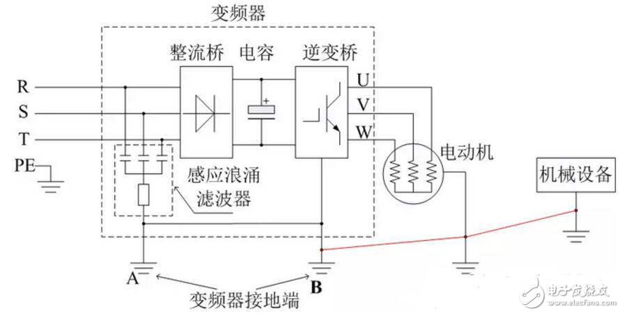
6) Starting from the needs of safety and noise reduction, in order to prevent leakage and interference from intruding or radiating out, it must be grounded. According to the electrical equipment technical standards, the grounding resistance should be less than or equal to the value specified in the national standard, and a thicker short wire should be connected to the dedicated grounding terminal PE of the inverter. When the inverter and other equipment or multiple inverters are grounded together, each equipment should be connected to the ground separately. It is not allowed to connect the ground terminal of one device to the ground terminal of the other and then ground it.
2. Control circuit terminals1) When using contact input, use a contact with high contact reliability.
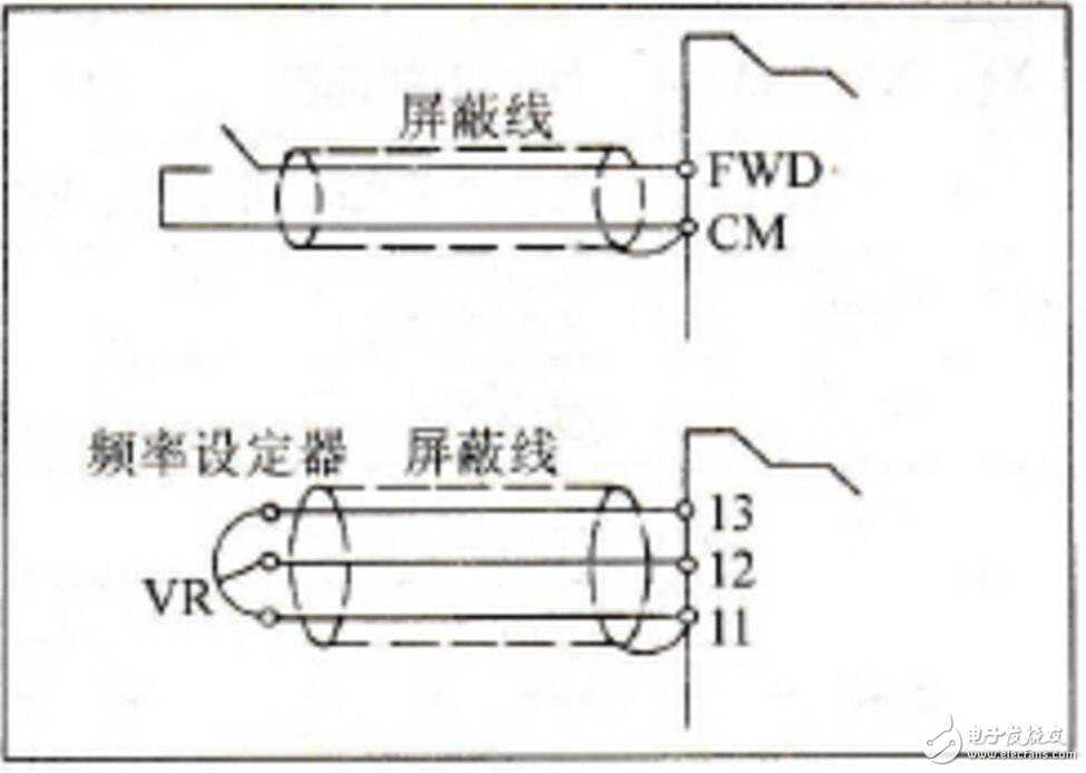
2) When leaving the factory, FWD-CM is connected with a short-circuit strip. After power on, just press the RUN button on the touch panel to run forward, and press the STOP button to stop running (in the touch panel operation mode).
3) When leaving the factory, the external alarm input terminal THR-CM has been connected with a short-circuit strip. When using it, the short-circuit strip should be removed and connected in series with the abnormal contact of the external equipment. If there is no such contact, do not remove the short-circuit strip.
4) The analog frequency setting terminals (13, 12, 11, C1) are the terminals for connecting the analog voltage, current, and frequency setting device (potentiometer) to be input from the outside. When setting contacts on this kind of circuit, use a tiny signal The paired contacts.
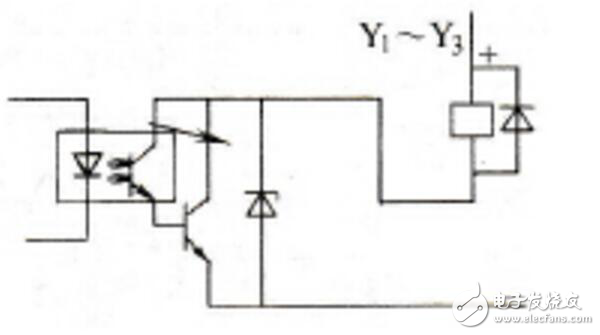
5) The coils of contactors, electromagnetic relays and other types of electromagnets in the variable frequency speed regulation system all have a large inductance, which will generate a high induced electromotive force at the moment of switching on and off, which will form in the circuit The high peak surge voltage affects the normal operation of the inverter. Absorption circuit can be used to control. When the open-collector output terminal is connected to a control relay, a surge-absorbing diode can be connected to both ends of the excitation coil, as shown in the figure.
6) The connecting wires on the control circuit terminals should be shielded wires of 0.75mm and below or twisted polyethylene wires.
7) The wiring of the shielded wire is as shown in the figure below. Connect one end to their respective common terminals (11, CM), and leave the other end unconnected.
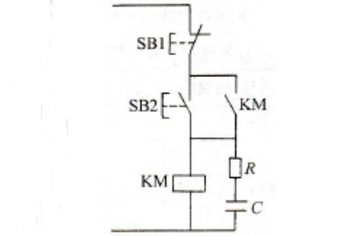
RC surge voltage absorption circuit can also be connected in parallel at both ends of the coil, as shown in the figure below. It should be noted that the wiring of the RC surge voltage absorption circuit cannot exceed 20cm.
1) Due to the leakage current in the inverter, in order to prevent electric shock, the inverter and the motor must be grounded.
2) Dedicated grounding terminal for inverter grounding. To connect the ground wire, use tin-plated crimp terminals. When tightening the screws, be careful not to damage the turnbuckles.
3) There is no lead in tin plating.
4) The grounding cable should be as thick as possible, and it must be equal to or greater than the specified standard. The grounding point should be as close as possible to the inverter. The shorter the grounding wire, the better.
What are the advantages of Explosion-proof Screen Protectors?
What is an Explosion-proof Screen Protector? This is a Soft Film made of imported PET material. It has very good flexibility and can help you solve the problems of tilting, white edges, and not suitable for curved screens. Can closely fit the curved edge of the screen.
The PET Screen Protector is made of imported materials from Korea. It is equipped with a proprietary "self-healing" function that can automatically repair minor scratches on the film. Daily protection measures to prevent accidental knocks and drops. The screen strengthens the screen and reduces the chance of cracking. Broken tempered glass is no longer replaced frequently.
1. Edge coverage: The Explosion-proof Screen Protective Film is made of PET flexible material, which is very suitable for the screen of your device, and 100% provides excellent edge coverage, and there is no gap between the edges of the device
2. High-definition resolution: high-definition display, true display of the original screen color.
3. Original touch experience: The oleophobic coating surface of the screen protector can provide your phone with original texture and perfect touch screen response speed. The Soft Film also has oleophobicity and water resistance, which can prevent unnecessary fingerprints.
4. Self-repairing scratches: The Screen Protection Film with self-repairing function can automatically repair tiny scratches and bubbles within 24 hours.
5. Anti-seismic and explosion-proof: PET material has high strength, flexibility and elasticity, which can fully decompose the impact force and prevent the mobile phone from breaking
Explosion-Proof Matte Protective Film,Matte Explosion-Proof Screen Protector,Anti-Scratch Matte Film,Anti-Impact Matte Film
Shenzhen TUOLI Electronic Technology Co., Ltd. , https://www.szhydrogelprotector.com