
1 Introduction
The use of car headlights for road lighting during night driving is directly related to the safety of driving, and the performance of headlamps is one of the causes of night traffic accidents. At present, most of the headlight sources use conventional light sources, such as incandescent lamps, halogen lamps, and High Intensity Discharge Lamps (HID). These lamps have a short life span, and incandescent lamps and halogen lamps have a life of only two thousand to three thousand hours. The HID light source has a slightly longer life, but it is only about 8,000 hours. Therefore, a new light source with a long life span will have a positive effect on improving lighting performance and reducing the occurrence of night traffic accidents.
Light Emitting Diode (LED) is a new era light source with tens of thousands of hours of life. In addition, LED has high luminous efficiency, compact size, short switch response time, impact resistance and vibration, etc. compared with traditional light sources. The advantages are therefore very suitable as a light source for automotive headlamps.
However, like traditional light sources, the use of LEDs as a light source still requires special secondary optical design. The most complicated one is the light distribution design of automotive low beam.
In general, the optical design ideas of LED low beam lamps can be divided into three types: refractive, reflective and hybrid. At present, the common design methods are the projection type of the baffle and the reflection type using the block design. Both methods have disadvantages. The optical system efficiency of the former may be greatly affected by the baffle shading, while the latter has a volume. Too big a disadvantage. In this paper, the hybrid LED low beam design is carried out by the free-form surface method. The key point is the design of the lens part of the free-form surface. The purpose is to achieve high optical system efficiency while maintaining compact size. After simulation, the design results are in line with the national low beam light distribution standard. I hope this paper can provide a new idea for the LED low beam optical design method.
2 headlights low beam light standard
According to the requirements of national standards, the low beam light used as the illumination means used when the car is driving at low speed at night should have sufficient illumination and can not produce strong glare to the oncoming driver or pedestrian. In this regard, GB25991-2010 made a special specification, using a low beam light distribution standard with a clear cut-off line to meet the above requirements. The test method for the low beam lamp is measured on a vertical plane light distribution screen 25m ahead of the lamp reference center. The illumination of each test point and area should meet the requirements of Table 1. The position of the test point and the test area is shown in Figure 1. Show.
Table 1 GB25991-2010 headlamp low beam light distribution test standard
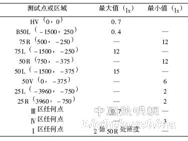

Figure 1 GB25991-2010 headlamp low beam light distribution test standard
3 free surface design method
A free-form surface is a surface that is irregular or difficult to describe with a unified equation. By applying a freeform surface, you can arbitrarily control the angle of light and distribute the light intensity. The flexible application of free-form surfaces can make the structure of the lighting system more compact and improve the utilization of light energy. In addition, it can reduce the appearance of discontinuous surfaces and facilitate processing.
The basic design idea of ​​constructing a free-form surface in this paper is to obtain the tangent vector at the point on the surface based on the vector relationship between the incident light and the outgoing light at a certain point on the surface, and solve the entire surface in combination with the boundary condition.
First consider a simple optical system consisting of a light source, a curved surface, and an illuminated plane. As shown in Figure 2, the coordinate system is established with the light source as the origin, assuming that a light emitted from it is incident on the surface of the surface p and then refracted perpendicular to z. The point t on the target surface of the axis. Incident ray vector at point p  Exit ray vector
  And the normal vector at that point
  Satisfy the refractive formula:

Figure 2 optical system schematic

It is then necessary to determine the energy correspondence between the incident light and the outgoing light. Naturally, consider an energy mapping method of u→y, v→x. Without considering the loss of light energy such as reflection, according to the law of conservation of energy, the incident light energy on the curved surface should be equal to the energy of the outgoing light, thus

Where I(u,v) is the light intensity function, and E(xt,yt) is the illuminance on the illuminated plane. From this relation, the expression of t-point coordinates expressed by u,v can be obtained, that is, Xt=f (u,v), Yt=g(u,v), substituted into the normal vector expression of çN, the freeform surface can be solved by numerical solution combined with the boundary conditions set by itself.