
1, oscilloscope amplitude frequency characteristic curve based on RC theoretical model
The bandwidth of the oscilloscope is called the first indicator of the oscilloscope, and the amplitude-frequency characteristic curve of the oscilloscope directly proves whether the oscilloscope bandwidth metric meets the requirements, and represents the important characteristics of the oscilloscope analog front-end amplifier.
When the oscilloscope inputs a sine wave with a constant amplitude but a varying frequency, the peak-to-peak value measured by the oscilloscope will vary with the input frequency. The magnitude of this amplitude as a function of frequency is the amplitude-frequency characteristic of the oscilloscope. In fact, the phase-frequency characteristics of the oscilloscope's amplitude-frequency characteristics are also mentioned in the discussion of signal fidelity of high-end oscilloscopes.
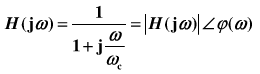
From a mathematical point of view, the oscilloscope's frequency response function H(jw) is equal to the ratio of the Fourier transform Y(jw) of the output y(t) to the Fourier transform X(jw) of the input x(t): H(jw) = Y(jw) / X(jw), generally H(jw) is a complex number whose mode is "amplitude-frequency characteristic" and its amplitude is "phase-frequency characteristic". A graph that represents amplitude-frequency characteristics by logarithmic coordinates is called a Bode plot.
It is well known that the analog front end amplifier of an oscilloscope is a low pass filter characteristic. The low-pass filter is equivalent to the first-order RC circuit model as shown in Figure 1.
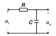
Figure 1 First-order RC circuit model of low-pass filter
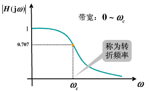
Figure 2: The amplitude-frequency characteristic curve of the low-pass filter
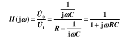
The transfer function of the RC circuit is:
Assumption:
Then the transfer function can be written as:
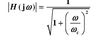
The amplitude-frequency characteristics are:
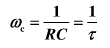
According to this, the amplitude-frequency characteristic curve of the first-order RC circuit is shown in Fig. 2. The corner frequency point in the figure is that the output voltage is reduced to 70.7% of the input frequency, which is the -3dB frequency point. The analog bandwidth of the oscilloscope is determined by this turning frequency point.
2, the different shapes of the amplitude-frequency characteristic curve
It is particularly emphasized that the amplitude-frequency characteristic curve of FIG. 2 is only a theoretical amplitude-frequency characteristic curve obtained based on the transfer function derived from the RC circuit, and its shape is a Gaussian response curve. In fact, the shape of the amplitude-frequency characteristic curve of an oscilloscope cannot be such a perfect Gaussian response. Different models of oscilloscopes may use different shapes of amplitude-frequency characteristic curves, and some use brick-walled (rectangular) amplitude-frequency characteristics, some use fourth-order Bessel curves, and some use Gaussian curves. But just approaching the shape of these ideal curves.
In the early years, oscilloscope suppliers wrote that the brick wall curve is the most perfect, because the distortion of the amplitude of the low-frequency signal is small, but the attack is accompanied by the serious phase distortion of the brick wall curve, but also Oscilloscope vendors emphasize that Gaussian curves are best suited for measuring pulse fast edge signals because the "tail" of the bandwidth is long and can contain more signal energy, but the attack is Gaussian response is the "nightmare of measuring high-speed signal eye diagram" "Because the IF portion of the high-speed signal is severely attenuated, the most dominant frequency component of the high-speed signal is below the IF portion. There are also oscilloscope manufacturers who have long and cumbered to explain that the fourth-order Bessel is the most suitable for measuring high-speed serial signals.
In order to be able to use different amplitude-frequency characteristics for different applications, oscilloscope vendors simply let the user select a certain amplitude-frequency characteristic curve in the oscilloscope menu. To this end, the supplier published a serious technical white paper to explain the DSP. The application of correcting the shape of the amplitude-frequency characteristic curve at the front end of the oscilloscope simulation. However, the company's approach has encountered trouble in the local competition in the Chinese market. Therefore, the friend "attacks" that the company's oscilloscope analog front end is implemented with "software", so there must be problems. Clouds like this... These unreasonable and boring attacks are often accepted by some customers. The inspiration for this is that when some oscilloscope vendors try to bring users into advanced cognitive mode through the "MarkeTIng Talking" tool to gain insight into the details of the oscilloscope, it may be counterproductive.
We can further derive the relationship between the rise time and bandwidth of the oscilloscope: rise time = 0.35 / bandwidth. This 0.35 is also derived based on the RC circuit. However, the actual oscilloscope analog front end is not likely to be a standard RC circuit model. The amplitude-frequency characteristic curves have different shapes. The actual rise time and bandwidth may be different between 0.4, 0.45, and 0.5. Different amplitude-frequency characteristics may correspond to different rise times. The actual oscilloscope amplitude-frequency characteristic curve and rise time are obtained by metrological calibration.
-------------------------------------------
- This article is selected from the "Test and Measurement Special Issue" in May.
Terminals refer to terminal Connectors,which are divided into single holes,double holes,sockets, hooks etc.From materials:copper plating, copper galvanizing, copper,aluminum,iron,etc.Their role is mainly to transmit electrical signals or to conduct electricity.
Our company's Terminal Connectors are divided into these series(as follow),which are hot-selling in recent few years:
Copper Tube Connectors(GTY)
JGK End Junction Terminal Connectors
JGA End Junction Terminal Connectors
JGY End Junction Terminal Connectors
JGB End Junction Terminal Connectors
DTL-1 Aluminium-Copper Terminal Connector
DTL-2 Aluminium-Copper Terminal Connector
DT Copper End Junction Terminals
DL Aluminium End Junction Terminals
Bus-Bar Terminal Connector
SM Insulate Terminal Connectors
One hole long barrel copper lugs
Two holes long barrel copper lugs
Terminal Connectors,Sc Cable Lug,Cable Lug,Terminal Lug
Ningbo Bond Industrial Electric Co., Ltd. , https://www.bondelectro.com