
1. Accurate measurement of high-value resistance (single bridge)
2. Grasp the principle and method of measuring the bridge resistance
Second, the experimental principleResistance is one of the basic components of the circuit, and resistance measurement is a basic electrical measurement. Measuring resistance with voltammetry, although simple in principle, has systematic errors. When it is necessary to accurately measure the resistance, a Wheatstone bridge must be used, and the Wheatstone bridge is suitable for measuring the median resistance (1 to 10 Ω).
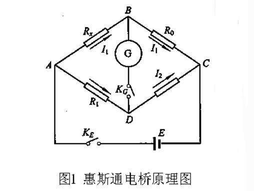
The principle of the Wheatstone bridge is shown in Figure 1. The standard resistors R0, R1, R2 and the resistance RX to be measured are connected into a quadrilateral shape, and each edge is called an arm of the bridge. Power supply E is connected between diagonals A and C, and galvanometer G is connected between diagonals B and D. Therefore, the bridge consists of three parts: four arms, a power supply, and a galvanometer. When the switches KE and KG are turned on, currents flow through the branches. The galvanometer branch serves to communicate the two branches of the ABC and the ADC. It looks like a “bridge†and is called “electricity.†bridge". Adjusting the size of R0, R1 and R2 appropriately can make no current pass through the bridge, that is, the current through the galvanometer IG=0. At this time, the potentials of the two points B and D are equal. This state of the bridge is called equilibrium. At this time, the potential difference between A and B is equal to the potential difference between A and D, and the potential difference between B and C is equal to the potential difference between D and C. Let the currents in the ABC branch and the ADC branch be I1 and I2 respectively, which is obtained by Ohm's law:

Dividing
(1) The type is called equilibrium condition of the bridge. From (1)
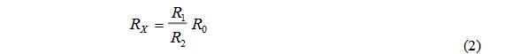
That is, the resistance RX to be measured is equal to the product of R1/R2 and R0. R1/R2 is usually called a ratio arm and R0 is called a comparison arm.
Third, experimental equipmentBox DC single-arm bridge, a number of wires, resistance to be measured.
Fourth, the experiment content and steps1. Select "Single Bridge" for both RN and function selector.
2. Turn on the power, press the 2mV file, adjust the zero potential, and zero the reading.
3. Press the voltmeter "Access button", 200mV button.
4. Initial Rx access R3. Set R1, R2 according to the Rx/R3 ratio.
5. Press the B, G buttons to gradually adjust R3 (from high to low, making V approximately equal to 0).
6. Repeat the above steps to measure the log data multiple times.
V. Experimental data and processing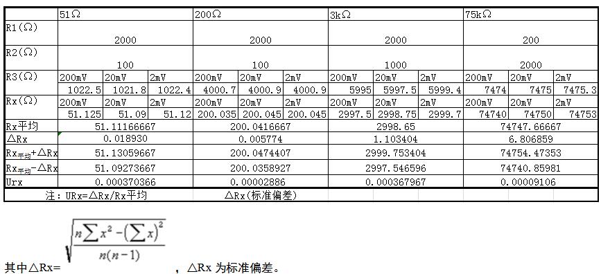
1. The power supply instrument has a long trial time and the voltage is too small.
2. Abrasion of the wire causes uneven distribution of resistance.
3. The galvanometer sensitivity can cause accidental errors to increase.
4. The resistor is used for a long time and is damaged.
5. The error of the component itself.
Guangzhou Yunge Tianhong Electronic Technology Co., Ltd , https://www.e-cigarettesfactory.com