
The application of CAN bus seems to be more and more extensive nowadays. Our factory equipment has been upgraded from the initial ARM9 and ARM7 platform to the Cortex A8 and Cortex M3 platform, and now to the Cortex M4 platform, we have carried out a series of products around CAN. Development, the stability of the CAN bus is beyond doubt.
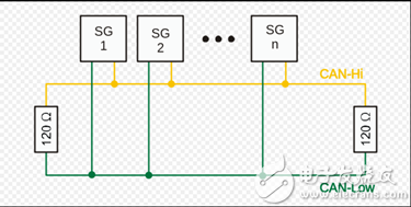
CAN bus physical structure and characteristics CAN bus networkThe CAN bus network is mainly connected to CAN_H and CAN_L. Each node implements serial differential transmission of signals through these two lines. In order to avoid signal reflection and interference, it is also necessary to connect a 120 ohm termination resistor between CAN_H and CAN_L, but why? Is 120 ohms? That's because the cable's characteristic impedance is 120 ohms .
The role of the CAN transceiver is to convert between logic levels and signal levels.
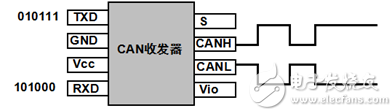
That is, from the CAN control chip output logic level to the CAN transceiver, and then through the CAN transceiver internal conversion logic level converted to a differential signal output to the CAN bus, the nodes on the CAN bus can determine whether they need the data on the bus . The specific discipline is defined as follows:
The CAN bus uses the non-return to zero code filling technique , which means that the signal on the CAN bus has two different signal states, which are Dominant logic 0 and recessive logic 1, and each signal transmission. There is no need to return to logic 0 (dominant) levels after completion.
Bit stuffing rules : The sender automatically inserts supplemental bits in the bitstream as soon as it detects that there are 5 consecutive bits of the same value in the bitstream.
Observe the following figure:
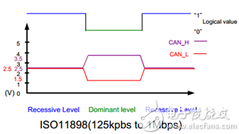
It can be seen that when the first segment is recessive, the levels of CAN_H and CAN_L are almost the same, that is, when the levels of CAN_H and CAN_L are close or even, the bus is recessive, and the two lines are When the point difference is large, it becomes dominant, according to the definition:
When CAN_H-CAN_L < 0.5V is recessive, the logic signal appears as "Logic 1" - high.
When CAN_H-CAN_L > 0.9V is dominant, the logic signal appears as "Logic 0" - low level.
The following is a summary of the correspondence between differential signals and implicitness:
status
Logic signal
voltage range
Dominant
0
CAN_H-CAN_L > 0.9
Recessive recessive
1
CAN_H-CAN_L < 0.5
From the above analysis we can know:
The bus line uses the "line and" rule for bus punching. That is, 1&0=0; so 0 is dominant.
The implication of this sentence is that if only one node on the bus pulls the bus low (logic 0), ie, the dominant state, the bus is low (logic 0), ie, the dominant state, regardless of the bus. How many nodes are in a recessive state of transmission (high level or logic 1), and only if all nodes are high (recessive), the bus is high, that is, recessive.
Communication speed and communication distanceThe following SAE J2411 is the American automotive standard.
Types of
standard
The highest rate
description
High-speed CAN
CAN/ISO 11839-2
1 Mbit/s
The most common type of CAN bus
Low speed CAN
ISO/ISO 11839-3
125Kbit/s
Fault tolerance, still working when a bus is short-circuited
Single line CAN
SAE J2411
50Kbit/s
High-speed mode can reach 100Kbit/s mainly used in cars, such as general-purpose company
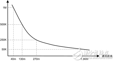
The maximum transmission distance of any two nodes on the CAN bus is related to its bit rate, as shown in the following table:
Bit rate /kbps
1,000
500
250
125
100
50
20
10
5
Maximum distance /m
40
130
270
530
620
1300
3300
6700
10000
The maximum communication distance here refers to the distance between two nodes on the same bus. It can be seen that the lower the speed is, the farther the communication distance is, ie , the communication distance of the CAN bus is inversely proportional to the baud rate . The maximum transmission distance is 10 km at a bit rate of 5 kbits per second. Among them, the commonly used project is a communication rate of 500K per second . This rate is also very reliable during actual testing.
If you want more distant transmission (greater than 10 km); consider a device consisting of multiple CAN controllers or interface chips with other communication protocols (such as 485 or TCP/IP). Distance communication needs.
Key Concepts of CAN Bus ArbitrationAs long as the bus is free, any node on the bus can send messages. If two or more nodes start to transmit messages, there is a possibility of bus access violation. But CAN uses a bit-by-bit arbitration of identifiers to solve this problem.
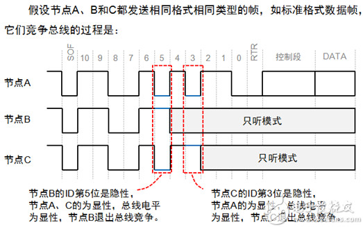
During arbitration, each transmitter compares the transmitted level with the monitored bus level. If the levels are the same, this unit can continue to send. If a "recessive" level is sent and a "dominant" level is monitored, the node loses arbitration and must exit the transmission state . If an unmatched bit occurs instead of during arbitration, an error event is generated.
The smaller the frame ID, the higher the priority. Since the RTR bit of the data frame is a dominant level and the remote frame is a recessive level, the data frame takes precedence over the remote frame when the frame format and the frame ID are the same, and the IDE bit of the standard frame is a dominant level. The IDE frame of the extended frame is a stealth level. For standard frames and extended frames with the same first 11-bit ID, the standard frame has a higher priority than the extended frame .
CAN bus protocolThe CAN bus is a broadcast-type bus, so any node on the bus can listen to data transmitted on the bus . In other words, the transmission on the bus is not a point-to-point, but a point-to-multipoint transmission, where the multiple points mean all the nodes on the bus. But how do the nodes on the bus know what data is transmitted to them? The CAN bus hardware chip provides a function called local filtering. This local filtering function can filter out some data that is not related to itself and retain some information related to itself .
CAN message mechanismThe CAN standard defines four message types. Each message is controlled by an Arbitration mechanism to enter the CAN bus, and each message is marked with priority. In addition, the CAN standard also defines a series of error handling mechanisms.
Four Message Types of CAN Messages:
Data frames: Data frames transmit data from the sender to the receiver.
Remote Frame: The bus unit sends a remote frame requesting the sending of a data frame with the same identifier.
Error Frame: Any unit will send an error frame if it detects a bus error.
Overload frames: Overload frames provide additional delay between adjacent data frames or remote frames.
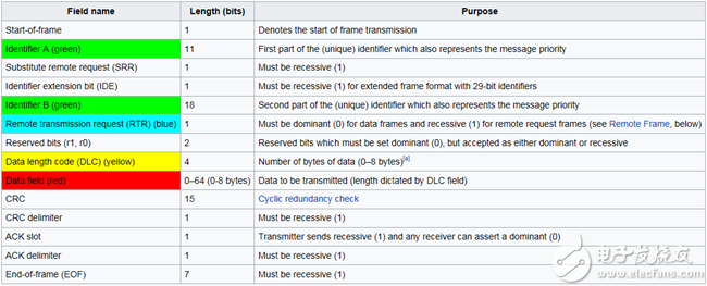
Data FrameThe following figure shows the basic format:
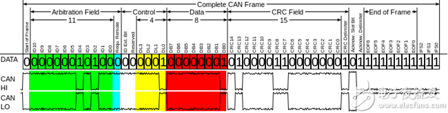
There are two formats of standard frame and extended frame on the CAN bus. The difference between the two formats lies in the format of the arbitration field. The difference between the two formats can be clearly seen in the following two tables. The first table below is the standard frame. (CAN2.0 A), the second is the extension frame (CAN2.0 B):
The following is the extended frame format (CAN2.0B):
among them
SOF starts at frame
SRR "replaces remote request bits
IDE is extended identifier bit
RTR is a remote transmission request bit
CRC delimiter is a CRC delimiter.
ACK delimiter is the reply delimiter.
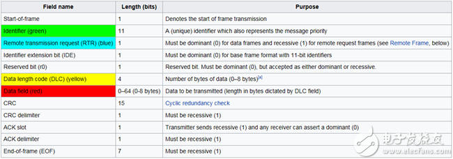
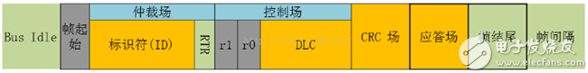
We can see that the basic frame format in the above figure can be summarized as the following fields:
area
description
Arbitration domain
The arbitration domain determines the priority when two or more nodes on the bus contend for the bus.
Data field
Contains 0 to 8 bytes of data.
CRC field
A 15-bit checksum is included, and the checksum is used for error detection.
Response slot
Any controller that has correctly received a message sends an acknowledgment bit at the end of each message. The sender checks whether the message has an acknowledgment bit, and retransmits the message if it does not.
Remote frameAs a data receiver station, by sending remote frames, its resource nodes can be started to transmit their respective data. Remote frames and data frames are very similar, except that the remote frames have no data fields.
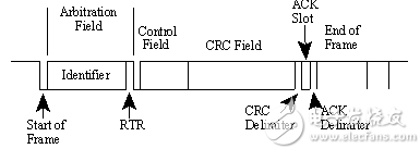
The above figure shows the frame format of the remote frame. There is no remote frame with respect to the data frame, but it should be noted that the RTR bit should be set when the remote frame is sent, indicating that the remote frame is sent. The figure below shows this structure more clearly.

The error frame is sent out when a certain node of the bus detects an error, it will cause all nodes to detect an error, so when any node detects an error, other nodes on the bus will also send an error frame . The CAN bus has designed a detailed error counting mechanism to ensure that the CAN bus does not crash due to repeated transmission of error frames by any one node.
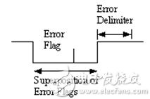
As shown in the figure above, the error flags and error delimiters are composed. The high and low levels represent the recessive and the dominant, respectively . The error flags are the superpositions of the error flags sent by all the nodes. The following figure more clearly shows the distribution of individual data bits:

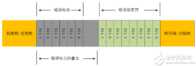
The following is a summary of the definition of each section through the following data structure block diagram:
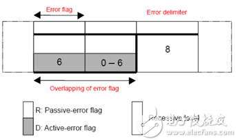
There are two forms of error flags:
Active error flag, which consists of 6 consecutive dominant bits 0, which is the error flag that the node actively sends.
Passive error flag, which consists of 6 consecutive recessive bits 1 unless overridden by other nodes' dominant bits.
Just saying that an error was detected on one node will cause all nodes on the bus to detect an error and send an error flag. Why?
Because the format of the error flag on a single node violates the bit-filling rule from the start of the frame to the CRC delimiter, the fixed format of the ACK field or the end of the frame is also violated. The following is a brief explanation of the lower filling rules.
Bit stuffing rules: The sender automatically inserts supplemental bits in the bitstream as soon as it detects that there are 5 consecutive bits of the same value in the bitstream.
Note: Bit stuffing rules are only for data frames and remote frames, error frames and overloaded frame formats are fixed.
So all other nodes will detect the error condition and start sending the error flag, so the error frame is the result of the superimposition of different error flags for each station.
When a node sends an error frame (with an error flag) and other nodes receive an error frame and detect an error condition, an error frame is sent to indicate the error by sending a "passive error flag."
Bad delimiter:
After the error flag is transmitted, each station sends a recessive bit and keeps monitoring the bus until a recessive bit is detected, and then starts sending the remaining 7 recessive bits.
Overload frameThe overload frame is a frame used by the receiving node to inform the sending node of its own receiving capability.
An overloaded frame means that a receiving node has no time to process the data. It is hoped that other nodes will send data frames or remote frames slowly, so tell the sending node that I have no ability to process the data you sent.
Overload frames are similar to error frame structures, including overload flags and overload delimiters. There are 3 conditions that can cause overload:
For the internal reason of the receiver, it needs to delay the next data frame or remote frame.
A dominant bit is detected in the first and second bits of the intermittent field (see the following interframe space) (intermittent fields are recessive)
If the CAN node samples a dominant bit logic 0 in the error delimiter or the eighth (last bit) of the overload delimiter, the node will send an overloaded frame and the error counter will not increment.

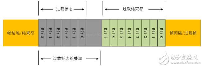
The figure above clearly shows that the overload flag is composed of six dominant bits, and the superposition part is the same as the "active error" flag. The overload flag destroys the fixed format of the intermittent field. Therefore, all other nodes have detected an overload condition and issued an overload flag together.
Overload delimiter:
That is, the overload terminator in the above figure. After the overload flag is transmitted, the node keeps listening to the bus until it detects a transition from a dominant bit to a recessive bit. When such a transition is detected from the bus, it signifies that each node completes the transmission of its own overload flag and starts sending the remaining seven recessive bits at the same time.
Interframe SpaceInterframe space is said to be the interval between the frame and the frame, but this interval exists only in the data frame and the remote frame in the CAN frame . The other frames are not necessarily separated by the space between the frames, but other forms Or there is no interval directly. For example, there is no inter-frame space between overload frames and error frames. There is an interval between overload frames but not space between frames.
The inter-needle space referred to here includes "intermittent" and "bus free" bit fields. If it is a "passive error" station that sends a previous message, it also includes a bit field called "pending transmission."
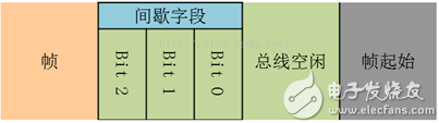
If the station is not a "passive error" or a station that is a receiver of a previous message, the format of the inter-frame space is as follows:

If the " passive error " station, if you want to send 8 recessive levels, send other frames, the inter-frame space format is shown in the figure below, which includes the pending transmission,
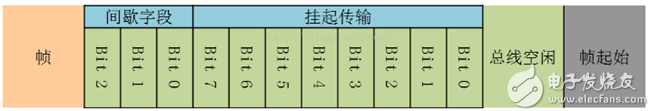
can be seen
The intermittent field has 3 recessive bits.
Especially during the interval, all nodes are not allowed to transmit data frames and remote frames, the only thing that is seen is to indicate an overload condition.
Bus idle :
As long as the bus is free, any node can send data to the bus and is the first bit to begin after the pause. Once a dominant bit, a logical "0", is detected on the bus, it can be considered as the beginning of the frame.
Suspend transmission
After the "passive error" node sends the message, it sends out eight recessive bits following the pause before the next message starts to be sent or before confirming that the bus is free . If there is a message sent from other nodes at this time, this node becomes the receiver.
Error handling mechanism Error detectionSubscripts are several error types:
Type of error
Error conditions
Error domain
Frame measurement unit
Bit error
Bit error
The transmitted bit value does not correspond to the monitored bit value (except for stuffing bits and ACK bits)
Data Frame (SOF~EOF)
Remote Frame (SOF~EOF)
Error frame
Overload frame
Sending unit
Receiving unit
Stuff error
6 consecutive levels detected
Data Frame (SOF~CRC)
Remote Frame (SOF~CRC)
Sending unit
Receiving unit
CRC error
The calculated result is different from the received CRC
Data Frame (CRC)
Remote Frame (CRC)
Receiving unit
wrong format
Form Error
Invalid bit in a fixed format location
Data Frame:
(CRC Delimiter, ACK Delimiter EOF)
Remote frame:
(CRC Delimiter, ACK Delimiter)
Error frame:
(Error Frame Delimiter)
Overload frame:
(Overload Delimiter)
Receiving unit
Answer error
Acknowledgment
The bit monitored by the sender in the reply gap is not dominant, ie logic 0, the sender detects a reply error.
Data frame (ACK slot)
Remote ACK slot
Sending unit
Error countThe following is the error count table:
Error conditions
Transmit Error Counter
Receive Error Counter
1
RECEIVER detected a bit Error, except sending ACTIVE ERROR FLAG and OVERLOAD FLAG
-
+1
2
TRANSMITIER Send ERROR FLAG
+8
3
TRANSMITTER detected BIT ERROR when sending ACTIVE ERROR FLAG OVERFLAG
+8
4
BIT ERROR detected when RECEIVER sends ACTIVE ERROR FLAG or OVERFLAG
+8
5
After a frame was successfully sent (get ACK and know that END OF FRAME completes without error)
-1 IF TEC=0, TEC will not be changed
-
6
A frame was successfully received (know that the ACK field has not detected an error and successfully sent an ACK bit)
-
1. if 1 <= REC <= 127 -> REC-1
2. if REC = 0 -> REC = 0
3. if REC > 127 -> REC = a value
Between 119 to 127
7
128 consecutive 1s on the bus are detected, the "bus off" node is allowed to become no longer "bus off"
Cleared to TEC = 0
Cleared to REC = 0
Error suppressionIn order to prevent certain nodes from making mistakes, they always send error frames and interfere with the communication of other nodes. The CAN protocol specifies the three states and behaviors of nodes , as shown in the following figure:
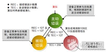
After a node is hung on the CAN bus, it is in the ACTIVE state; TEC>127 or REC>127 causes the node to enter the passive state; TEC>255 after the node is in the bus off state, that is, it is not allowed to send anything to the bus; The state node will return to the active state after detecting 128 consecutive 11 1s.
Home Audio Speaker,10 Woofer Speaker,10 Inch Woofer Speaker,Portable Woofer Speaker
Guangzhou Yuehang Audio Technology Co., Ltd , https://www.yhspeakers.com