With the growing severity of anti-terrorism situations at home and abroad and the frequent occurrence of various types of emergencies, higher requirements have been put forward for the armed police forces to complete tasks in a variety of complex and dangerous environments quickly and effectively. Traditional methods of reconnaissance have been unable to meet the needs of the situation. For example, major natural disasters have caused the rescue work to fail; counter-terrorism or assistance in arresting cannot effectively track suspects. The presence of an unmanned reconnaissance aircraft has brought convenience to the on-duty personnel. However, during the reconnaissance process, the vibration generated by the drone itself will cause image shooting to appear jittery. Therefore, the correct decision of the commander is greatly affected. Traditional autopilots use inertial measurement units to obtain aircraft attitude information, including angular speedometers (gyros) and accelerometers. The gyroscope is used to measure the attitude and angular velocity of the aircraft; the accelerometer is used to measure the projection of two horizontal directions under the general gravitational acceleration, and the current attitude of the aircraft can be converted through the triangular relationship, that is, the pitch angle and the roll angle. However, the attitude information measured by the accelerometer is very vulnerable to the vibration of the aircraft and the self-acceleration of the maneuvering flight. The measurement accuracy error is generally relatively large and the stability is poor, so that the reconnaissance effect is affected. In order to solve the drone's flight stability, an all-stride stabilization control system consisting of a three-axis gyro and an inclination Sensor was studied to improve the stability of the drone during mission execution.
l System FeaturesGyro and tilt sensors form a full-stall stabilization control loop. The gyro-measured angular velocity information is used as a stabilizing feedback control to make the aircraft more "insensitive" to manipulation, so that the aircraft roll angle and pitch angle are measured using the tilt sensor. Then, the angular rate information measured by the gyro and the attitude angle measured by the tilt sensor are subjected to a strapdown operation to obtain the fused attitude information. This more complex Strapdown algorithm can greatly improve the attitude accuracy.
2 attitude stabilization control law hardware designUAV attitude stabilization control belongs to inner loop control. It includes attitude maintenance and control, speed control and other modes. The inner loop control is based on the triaxial gyro and tilt sensor to acquire the flying attitude of the UAV, and through the control of the elevator and the rudder, the stability and control of the flying attitude are completed. The inner loop control is the core loop of flight control, and is also the basis for outer loop control such as flight altitude and track. The external loop control is based on the GPS position, heading signal, altitude sensor pressure altitude signal, and it calculates the planned route and actual route of the aircraft through the navigation control method.
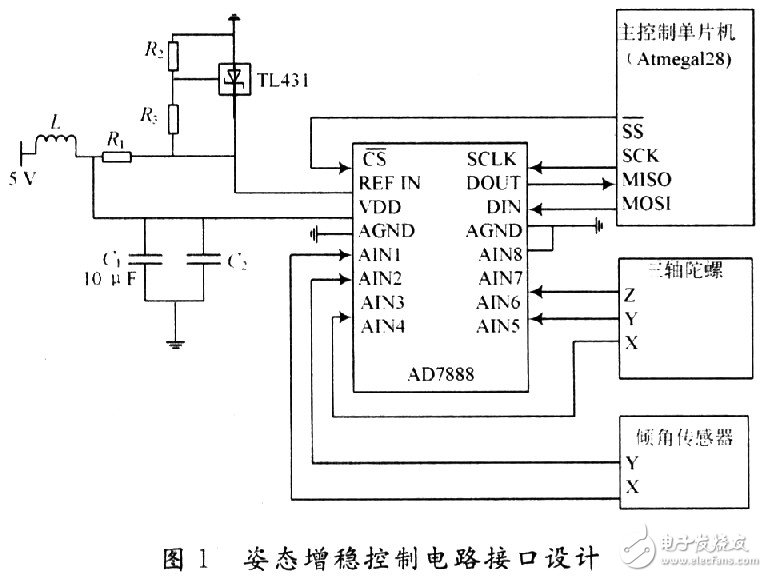
The UAV's internal loop control serves as the basis for the external loop control and plays a crucial role in its ability to stabilize the flight. In this system, the inner loop is a posture stabilization loop consisting of a three-axis gyro and an inclination sensor. Mainly by the main control microcontroller, A / D sampling chip, three-axis gyroscope and tilt sensor. The main control MCU is connected to the A/D sampling chip through an SPI serial bus. The A/D sampling chip obtains the angular and pitch angles of the three-axis gyroscope's angular rate and tilt sensor, and then performs attitude information fusion to obtain the unmanned. Pitch and roll attitude information. The main interface connection is shown in Figure 1.

In Figure 1, the AD7888 is a high-speed, low-power, 12-bit analog-to-digital converter capable of 125 KSPS transfer rate with eight analog input channels.  For the chip select pin, this pin has two roles, namely start the AD7888 converter and develop serial data transfer, and the microcontroller pin PB0 (
  ) Connected. SCLK is a serial clock input pin and provides a serial clock signal through the external microcontroller's ATmegal28 pin PB1 (SCK). DIN is the logic data input, and DOUT is the logic data output. It is connected with pins PB2 (MOSI) and PB3 (MISO) of ATmegal28.
The external reference voltage range is Vref to VDD (Vref=1.2 V). In order to obtain a stable reference voltage, a reference voltage circuit composed of TL431 is used. The TL431 produced by Texas Instruments (TI) is a three-terminal adjustable shunt reference source with good thermal stability. Its output voltage can be set to any value from Vref = 2.5 V to Vref = 36 V using resistors R2 and R3.
The microcontrollers ATmegal28 and AD7888 are connected via a serial communication interface SPI, which are configured as master and slave respectively. The SPI bus allows high-speed synchronous data transfer between the ATmegal28 and peripherals.
The three-axis gyroscope is mainly used to measure the angular velocity of the pitch, roll, and yaw angles of the drone during flight, and calculates the angle change according to the angular velocity integral. In this system, Panasonic’s EWTS82 (hereinafter referred to as S82) is used, and the principle is to convert the earth deflection force (Coryolith force) generated by the rotation of the tuning fork into an electric signal. The three-axis gyroscope is composed of a sensor device, a tuning fork drive circuit, and a signal processing circuit. This gyro is an analog device with a measurement range of +80 to -80(°)/s, single-supply (+5 V DC) power supply, and good zero-point drift suppression. In addition, its low price can greatly reduce development costs.
The tilt sensor uses the high-precision two-axis tilt sensor SCAL00T produced by VTI Technologies of Finland. The sensor is small in size and light in weight. It contains a silicon-sensitive capacitive sensor and an ASIC-specific integrated circuit. It has both internal temperature measurement and compensation functions and self-detection function. The maximum single-axis output range is about -40 to +40 °C, and the effective output range is - 30 to +30 °C. When the sampling frequency is 8 Hz and below, an output resolution of 0.002° can be obtained. The serial peripheral interface SPI has an output frequency of 500 kHz. The sensor element controls the frequency response and can withstand mechanical vibrations greater than 20 000 g. Its main features are: x, y dual axis high resolution bidirectional measurement, single power supply (+5 V DC) power supply, low operating current (3 mA), low noise, wide operating temperature range (-40 to +125 °C )Wait.
3 attitude stability control software designThe input of the entire flight control system is the flight state value collected by the sensor. The output is the control variable (rudder value and engine thrust) of the aircraft state equation. Therefore, the flight control system is essentially a multi-channel control system. Input/multiple output control system. Among them, the flight control system's core control loop is based on the attitude angle (pitch/roll angle) feedback signal based on the composition of the flight attitude stability and control loop, the inner loop.
On the basis of the inner loop, external loops such as altitude maintenance and track control were introduced.
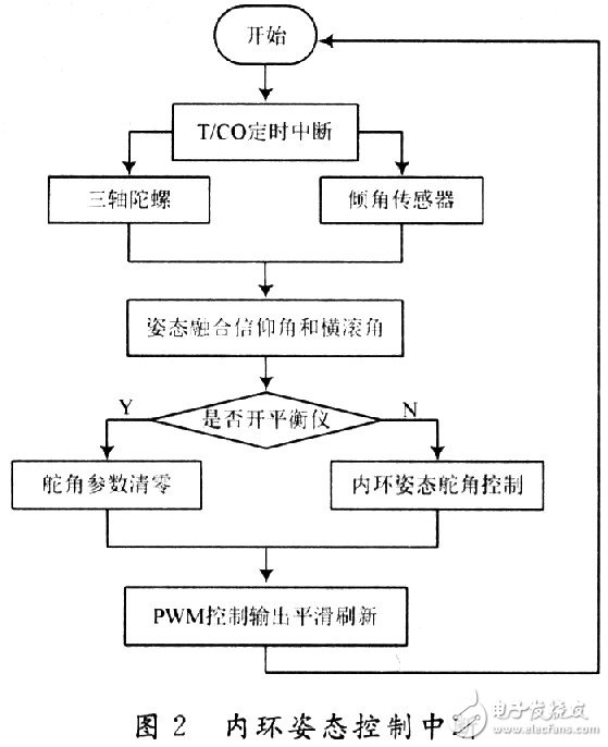
In the attitude stabilization control loop of the flight control system, the triaxial gyro feeds back the aircraft's angular rate of pitch, roll, and yaw in real time. In addition, the pitch angle rate and the roll angle rate of the three-axis gyro are separately connected to the pitch angle and the roll angle measured by the tilt sensor, and the posture is solved in a strapdown manner. The master microcontroller uses timing/counter O timing interrupts, and the internal loop attitude control is performed at intervals of 30 ms. The control flow is shown in Figure 2. Because of the symmetry of the aircraft along the longitudinal plane, drone flight control can be divided into relatively independent longitudinal control and lateral lateral control channels.

(1) Lateral lateral control channel: The lateral lateral movement of the UAV, that is, the rolling and yaw motion of the drone, is mainly achieved through the aileron channel. There are roll angle feedback and roll angle rate feedback in the lateral side control channels. These two items form the core circuit of the roll channel—inner loop. In addition, the heading deviation feedback only needs to be accessed when the UAV is used for directed direct flight, heading tracking or autonomous navigation, so as to stably control the flying course of the UAV; the lateral offset feedback is only when the UAV enters autonomous navigation. Need to be accessed to control drones to track pre-set flight routes; error integral feedback is only used when the UAV is doing directional flight to eliminate the effects of factors such as the asymmetry of the UAV and improve the unmannedness. The accuracy of aircraft heading control and the symmetry of left and right turns.
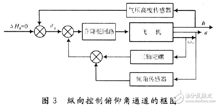
(2) Longitudinal control channel: Longitudinal movement of the UAV refers to the pitching and lifting motion of the UAV. The vertical motion of the drone is achieved by manipulating the drone's elevator. In the longitudinal control channel, there are pitch feedback and pitch rate feedback, which form the core control loop of the vertical channel—inner loop. In addition, there is feedback of altitude differences, and it is only necessary for the drone to make a high-flying flight to stabilize the flying height of the drone. The block diagram of the longitudinal control pitch angle channel is shown in FIG. 3 .

The UAV flight process can usually be divided into several relatively independent segments. One of the most basic autonomous flight projects can be divided into six flight segments: take-off phase, flight level, turn phase, return flight level, hover phase, and landing phase. The tasks of each flight segment are relatively independent, decomposing the complex flight states of each flight segment into several basic missions: level flight, turning, lifting, and so on. In this way, the basic flying missions such as flat flight, turning, lifting and lowering of the UAV are coordinated through relatively independent longitudinal control channels and lateral lateral control channels.
4 ConclusionIn the drone, the flight control system is the main component, and the attitude stabilization control is an effective method for the drone to perform various tasks smoothly. Based on the practical application, this paper describes in detail the hardware implementation and software design of the all-attitude stability-increasing control system based on three-axis gyroscope and tilt sensor, and applies it to a certain type of UAV to control the flight attitude in the system. The detailed analysis and research of the process and the law of inner-loop attitude control were carried out. After more than 100 test flights, the attitude stabilization control system based on three-axis gyros and tilt sensors not only satisfies the task requirements at the present stage, but also achieves good results. It provides a set of lines for the development and development of similar unmanned aerial vehicles. The effective method.

Absolute Linear Encoders,Custom Absolute Encoder,Rotary Encoder Magnetic,Miniature Absolute Encoder
Yuheng Optics Co., Ltd.(Changchun) , https://www.yhenoptics.com
