The design uses Samsung's S3C2440, combined with ICRoute's high-performance speech recognition chip LD3320, to perform hardware and software design of the speech recognition system. Under the embedded Linux operating system, the multi-process mechanism was used to complete the control of the voice recognition chip, ultrasonic ranging and PTZ, and the voice recognition technology was applied to the multi-angle ultrasonic ranging system. Through the test, the system can control the direction of the measurement by recognizing the voice instruction without manual intervention, and finally broadcast the measurement result through the voice.
1. introductionLanguage is an important means for humans to transmit information, and speech recognition is a key technology for achieving voice control. The adoption of embedded speech recognition technology makes the device has the advantages of low power consumption, easy use, and flexibility. It is free from the troubles of complicated buttons and buttons and plays an important role in serving robots, smart homes and consumer electronics.
2. System composition and principleSpeech recognition mainly includes two phases: training phase and recognition phase. In the training or recognition process, input speech must be preprocessed and feature extracted. In the training stage, several training speeches are input by the user, and feature parameters are obtained after preprocessing and feature extraction. Finally, a model library for training speech is established by modeling the feature parameters. The recognition stage is to measure the similarity between the feature vector parameters of the input speech and the reference model in the reference model library, and then output the input feature vector with the highest similarity as the recognition result, thereby achieving the purpose of speech recognition, as shown in FIG. 1 .
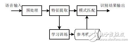
Speech recognition technology can be divided into two types: specific person identification and non-specific person identification. Specific person recognition refers to the need for training of the speech of the recognized person, and the identification target is a specific person. Non-specific person recognition means that the recognition target is for most users, and generally the voices of multiple persons are collected for recording, training, and learning. Achieve higher recognition rate.
In practical applications, there are two ways to realize embedded speech recognition based on modern technology: the embedded speech development package and the external speech recognition chip. The speech recognition system scheme of this article is based on the embedded processor S3C2440 as the core, and expands the non-specific human speech recognition chip LD3320, and combines the ultrasonic ranging module and the PTZ as the mechanical execution mechanism of the system. The system measurement process is as follows: First, according to the voice instructions to control the position and posture of the two degrees of freedom PTZ, so that the ultrasonic detector points in a specific direction, then turn on the ultrasonic detector, measure the distance of the obstacle in front, and finally convert the measurement result into a binary that can be played. The data stream completes the data playback through the LD3320's playback function.
3. Hardware circuit designThe hardware circuit mainly includes a voice recognition section, a main control section, an ultrasonic distance measurement section, and a servo control section, as shown in FIG. 2 . The processor is Samsung's S3C2440. The system clock frequency is up to 533MHz. It supports SPI, I2C, UART and other interfaces to meet the needs of the control system. The main control chip S3C2440 completes reading and writing operations to the voice recognition module through the SPI bus. The ultrasonic ranging section and the servo control section are controlled by the GPIO of the processor.
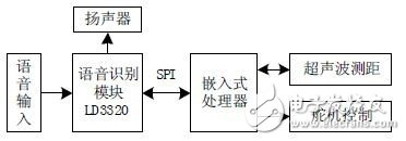
3.1 Speech Recognition Circuit Design
In order to enable the system to recognize the voice instructions issued by the operator, the design uses a non-specific human voice recognition chip LD3320 designed and produced by ICRoute, which integrates the voice recognition processing circuit and some external circuits, including AD, DA converters, microphones Interfaces, audio output interfaces, etc., do not need any external auxiliary chip such as Flash, RAM. Under the control of the main controller, the content added in advance to the identification list can be identified. The LD3320 data sheet issued by ICRoute is referenced in the design. The pins P0, P1, and P2 of LD3320 are connected to the embedded processor through the SPI interface. The control signals WRB, CSB, RSTB, and the interrupt return signal pin are INTB and processor. The S3C2440 is directly connected, as shown in Figure 3.
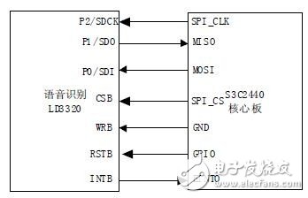
3.2 Ultrasonic Ranging and Servo Control Circuit Design
Ultrasonic distance measurement principle is relatively mature, the system uses ultrasonic ranging module HC-SR04. This module has two TTL level communication pins and is compatible with 3.3V level. Among them, the control port Trig sends a high level of more than 10us. The receiving port Echo will output a high level signal proportional to the distance. When the Echo has a high level output, the processor timer is turned on. When the port level transitions to a low level, the timer is turned off, and the obstacle distance can be calculated based on the timer value. Among them, the control port Trig and the receive port Echo are respectively connected to the GPG9 and GPG6 pins of the processor.
The sensing angle of the ultrasonic ranging module is less than 15°. In order to expand the sensing angle range of the ranging, the ultrasonic ranging module is mounted on a two-degree-of-freedom head, where the steering gear is SG90 (9G) and the rotation angle is 180°. The processor controls the two servos through GPB0 and GPB1 respectively to realize the rotation of the gimbal to measure obstacles in different directions, as shown in FIG. 4 .
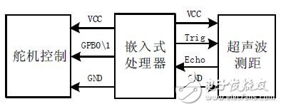
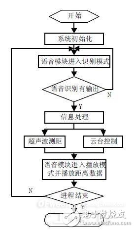
Based on the embedded Linux operating system, the system software implements such tasks as voice recognition, voice playback, ultrasonic ranging, and servo control. It uses the mechanism of the dock to allocate an independent process for each task so that the system can perform multitasking. Corresponding low-level driver programs are written for different functional modules, providing a call interface for the upper application program.
The system workflow is as follows: The processor performs general initialization of the voice recognition chip LD3320 through the SPI bus, so that the voice recognition chip enters the loop recognition mode, and the system processor repeatedly starts the voice recognition process. If there is a recognition result, the next recognition process is started after corresponding processing according to the recognition (for example, playing a certain sound as a response). The processor reads the C5 register's recognition result and analyzes it through the SPI bus, converts the voice command into the ultrasonic ranging and servo control signals, and completes the multi-directional ranging task, as shown in FIG. 5 .
4.1 Speech Recognition Function Programming
Voice recognition chip LD3320 features two functions of voice recognition and MP3 playback. When the function is switched, it must be initialized universally to perform a series of settings on the chip.
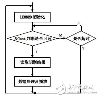
The driver workflow for the speech recognition function is Universal Initialization → Initialization for speech recognition → Write Recognition List → Start Identification → Response Identification Interruption. In order to increase the recognition success rate, “junk keywords†have been added to the identification list to absorb erroneous recognition. The upper application allocates separate processes for speech recognition. The ioctl() function controls the working state of the LD3320. The read() function can read the recognition result. The select mechanism is used in the program to implement non-blocking access to the read() function. At the same time, set the timeout time of the select monitoring. After the timeout, reinitialize the voice recognition chip LD3320 to prepare for the next speech recognition, as shown in Figure 6.
4.2 voice playback function programming
The LD3320 supports MP3 data playback. The sequence of operations in the program is: Universal initialization à Play mode initialization à Volume adjustment à Start playback, and prepare the interrupt response function to enable the interrupt enable bit. In the program, the voice MP3 data of numbers 0~9, "ten", "hundred", and "dot" are first converted into a standard C language array format file, and the file is added to the project for unified compilation. Then split the distance data that needs to be played, perform table lookup operations for each bit, and obtain the corresponding voice data. For example, the distance data 12.5 is split into: "1", "ten", "2", "dot", "5". Finally, the voice data obtained from the look-up table is combined in the left-to-right order and stored in the play data memory of the LD3320. When the play is completed, the chip will send an interrupt request and write the play data continuously in the interrupt response function until The sound data is played.
4.3 Ultrasonic Ranging and PTZ Control Program Design
The ultrasonic distance measurement function driver is a Linux character type driver, and uses the ioctl() function to perform timing control on the corresponding GPIO to complete the transmission and reception of ultrasonic waves. When the receiving port outputs a high-level pulse signal, the system interrupt is triggered and the high-level duration ΔT is calculated using a timer, and the distance S is measured according to formula (1). In the formula, V is the propagation speed of the ultrasonic wave, and the propagation speed of the ultrasonic wave in the air at normal temperature is 340 meters/second. In the application, the measured distance value can be read by the read() function.
S=VXΔT/2(1)
The two-degree-of-freedom gimbal consists of two servos that control the pan and tilt angles of the pan tilt. In the driver program, first open the timer PWM function and set the timer period, then map the timer interrupt function, and finally enable the timer so that the timer starts running. The program uses the ioctl() function to control the timer to output two PWM signals according to the voice command sent by the experimenter. It controls the rotation angles of the two servos, and finally synthesizes the motion into the pose of the head.
5. ConclusionThis article describes an application and implementation of embedded speech recognition technology in ultrasonic ranging systems. Experimenters can use pre-defined voice instructions (such as "start measurement", "upper left", and "front") to achieve Control the system and use ultrasonics for distance measurement. After the measurement is completed, the system feeds back the measurement results to the experimenter via voice playback to complete the human-machine interaction and improve the user experience. This system has the advantage of easy expansion and can be applied to other embedded control systems.
1.0mm (.039") Female Headers
Overview
Whenever there is a need for fitting small-sized connectors in compact devices, the 1.0mm pitch female header, or sometimes referred to as header connector, is ideally suited for this application. Not only does this female header space-savvy, but it is also designed for vacuum pick and place that makes it suitable for high volume automated manufacturing.Antenk offers these low profile, easy-install, SMT or THM miniature female connector plugs at high quality and affordable China-quoted price, for board-to-board connection, snuggly fitting the pins of a male header and acting as a receptacle.
Assembly and service is simple with either vertical (straight), elevated or at a right angle configuration/orientation, which can dissipate current of about 1.0 A or less in a tape and reel packaging. The filleted corners can also remove shadowing allowing optimization of LED output.
Also, the 1.0mm pitch female headers are made to work in Arduino boards, Arduino Pro and Arduino Mega with either single or double-row female headers, facilitating connections for programming and incorporation into other circuits. They have the perfect height for clearing the USB-B connector and great for stacking multiple shields.
Female header always called as [Header connector", Antenk provide widely range of header connector, from 2.54mm (.100″ inch) pitch to 1.0mm (.039″ inch) pitch. The number of pins (contacts) is from 2 to 40 pins per orw. There are three type: Straight (Dip Vertical), Right angle, SMT (surface mount).
If you can not find the items you interest from above items, welcome to contact us, and you will always get fully responsive from us.
Applications of 1.0mm Pitch Female Headers
Its small size is most suitable for PCB connections of small equipment and devices such as:
Arduino Boards
Architectural and sign lighting
Retail and display lighting
Fluorescent LED retrofit lighting
Cabinet or furniture lighting
Commercial / residential cove lighting
WiFi equipment
Gaming consoles,
Measurement instruments
Medical Diagnostic and Monitoring equipment
Communications: Telecoms and Datacoms
Industrial and Automotive Control and Test
Mount Type: Through-hole vs Surface Mount
At one side of this female header is a series of pins which can either be mounted and soldered directly onto the surface of the PCB (SMT) or placed into drilled holes on the PCB (THM).
Best used for high-reliability products that require stronger connections between layers.
Aerospace and military products are most likely to require this type of mounting as these products experience extreme accelerations, collisions, or high temperatures.
Useful in test and prototyping applications that sometimes require manual adjustments and replacements.
1.0mm vertical single row female header, 1.0mm vertical dual row female header, 1.0mm Elevated single row female header, 1.0mm Elevated dual row female Header, 1.0mm right-angle single row female header and 1.0mm right-angle dual row female header are some examples of Antenk products with through-hole mount type.
Surface-Mount
The most common electronic hardware requirements are SMT.
Essential in PCB design and manufacturing, having improved the quality and performance of PCBs overall.
Cost of processing and handling is reduced.
SMT components can be mounted on both side of the board.
Ability to fit a high number of small components on a PCB has allowed for much denser, higher performing, and smaller PCBs.
1.0mm Right-angle Dual Row female header, 1.0mm SMT Single row female header, 1.0mm SMT Dual row female header and 1.0mm Elevated Dual Row female Header are Antenk`s SMT female headers.
Soldering Temperature for 1.0mm Pitch Female Headers
Soldering SMT female connectors can be done at a maximum peak temperature of 260°C for maximum 60 seconds.
Orientation/Pin-Type: Vertical (Straight) and Right-Angle
1.0mm pitch female headers may be further classified into pin orientation as well, such as vertical or straight male header or right-angle female header.
Vertical or Straight Female Header Orientation
One side of the series of pins is connected to PCB board in which the pins can be at a right-angle to the PCB surface (usually called "straight" or [vertical") or.
Right-Angle Female Header Orientation
Parallel to the board's surface (referred to as "right-angle" pins).
Each of these pin-types have different applications that fit with their specific configuration.
PCB Connector Stacking
Profile Above PCB
This type of configuration is the most common way of connecting board-to-board by a connector. First, the stacking height is calculated from one board to another and measured from the printed circuit board face to its highest insulator point above the PCB.
Elevated Sockets/Female Headers
Elevated Sockets aka Stacked sockets/receptacles or Mezzanine are simply stacked female headers providing an exact distance requirement between PCBs that optimizes electrical reliability and performance between PCB boards.
Choosing this type of stacking configuration promotes the following benefits:
Connector Isolation - the contacts are shrouded preventing cable connection mishaps and good guidance for the mating header connectors.
For off-the-shelf wireless PCB module, stacking height is optimized with elevated sockets.
Offers superior strength and rigidity.
Polarisation prevents users from inverted insertion.
Single, Dual or Multiple Number of Rows
For a 1.0mm straight or vertical female header, the standard number of rows that Antenk offers ranges from 1 to 2 rows. However, customization can be available if 3 ,4 or n number of rows is needed by the customer. Also, the number of contacts for the single row is about 2-40 pins while for dual row, the number contacts may vary from 2-80 pins.
Pin Material
The pins of the connector attached to the board have been designed with copper alloy. With customer`s demand the pins can be made gold plated.
Custom 1.0mm Pitch Female Headers
Customizable 1.0 mm pitch female headers are also available, making your manufacturing process way faster as the pins are already inserted in the headers, insulator height is made at the right size and the accurate pin length you require is followed.
Parts are made using semi-automated manufacturing processes that ensure both precision and delicacy in handling the headers before packaging on tape and reel.
Tape and Reel Packaging for SMT Components
Antenk's SMT headers are offered with customizable mating pin lengths, in which each series has multiple number of of circuits, summing up to a thousand individual part number combinations per connector series.
The tape and reel carrier strip ensures that the headers are packaged within accurately sized cavities for its height, width and depth, securing the headers from the environment and maintaining consistent position during transportation.
Antenk also offer a range of custom Tape and reel carrier strip packaging cavities.
Pcb Header,1.0Mm Female Pin Header,1.0Mm Female Header Connector,1.0Mm Pcb Header,0.039" Female Headers,0.039" Pin Header, 1.0mm Female Pin Header SMT, 1.0mm Female Pin Header THT
ShenZhen Antenk Electronics Co,Ltd , https://www.antenkwire.com
