With the rapid development of science and technology, airplanes have put forward higher and higher requirements for airborne electronic systems. The improvement of aircraft performance depends to a large extent on the improvement of the performance of airborne electronic systems. In the onboard electronic system of the aircraft, the display system is the bridge between the aircraft and the pilot for human-computer interaction. It converts various flight parameters into visual information and displays it on the monitor. The pilot can read this information in real time to make judgments.
In this paper, the hardware circuit part of an airborne video graphics processing system is designed. The video graphics processing system is a subsystem of the airborne display system, which is used to display the video signal formed by superimposing high-pixel graphics and external input video on the airborne display. The system uses Xilinx's Virtex-5XC5VFX70T FPGA as the core processor, with a variety of peripheral video processing chips, and achieves multiple processing functions such as zooming, format conversion, and superimposing high-pixel graphics symbols on high-definition video, and has high real-time Sex.
1 System overview 1.1 System requirementsThe main function of the airborne video graphics processing system is to receive external video signals in multiple formats, generate dot matrix character signals, convert video formats, and output video signals that generate superimposed characters and external video.
The system receives PAL (Phase Alternating Line), DVI (Digital Visual Interface, digital video interface) format video signals and. PCI-E (Peri pheral Component Interconnect-Express, extended peripheral component interconnection standard) video signal, after the video is scaled, format converted, etc., superimposed on high-pixel graphics, and output the synthesized video signal as required.
1.2 Overall scheme designCombining system requirements, the overall design plan of the system is determined as follows: take Xilinx's Virtex-5 XC5VFX70T FPGA as the core processor, use its powerful logic resources and rich IP cores, with corresponding external circuits to construct a flexible and concise , Reliable embedded hardware module of airborne video graphics processing system. Utilize the Power PC 440 hard core processor embedded in XC5VFX707T, transplant the Vxworks operating system of American Wind River company on this processor, manage the network and PCI-E interface through the operating system, and realize on the basis of the operating system Corresponding graphics operation and video processing API (ApplicaTIon Programming Interface, application programming interface) function, the user's application program by calling the API function to build the final video output.
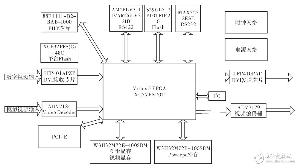
2 System hardware module design 2.1 Overall hardware architectureAccording to the design requirements, XC5VFX70T FPGA is selected as the core processor, which is manufactured with 65 nm process and is specially developed for embedded applications. The processor has a built-in PowerPC440 core with a clocked frequency of 550 MHz, PCI-E endpoints and Ethernet modules. The hardware part of the system also includes peripheral circuits such as the video codec chip, DDR2 video buffer, and PowerPC external memory. The hardware block diagram of the entire system is shown in Figure 1.

Figure 1 System hardware block diagram
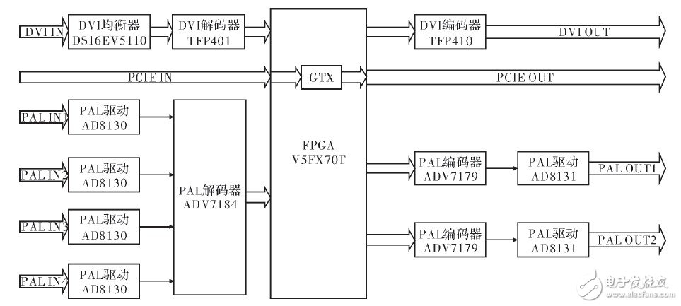
2.2 Video flow graphThe system is mainly used to receive, process and send various video signals. The video flow diagram in the system is shown in Figure 2. It can be seen from the figure that the system can receive 1 DVI video, 4 PAL video and 1 PCI-E video. After the video passes through a special decoder, the FPGA processes them, and then outputs the video signal through the corresponding video encoder. .

Figure 2 System video flow diagram
2.3 DVI video codec module designThe system’s DVI video decoding is implemented using TI’s DVI decoding chip TFP401, which meets the DVI1.0 specification, supports up to 1 600×1 200 resolution, and supports 24-bit true color video. In addition, considering the long distance between the airborne video signal source and the DVI receiver, the high-frequency component of the signal is attenuated more than the low-frequency component during long-term transmission, so an equalizer is added before the DVI input signal is decoded to achieve the equalization of the spectrum. , Reduce signal distortion. The system uses National Semiconductor’s DS16EV5110 to realize the spectrum equalization of the DVI video signal. The chip can set different equalization gains for each data channel of the DVI video signal. It has a high degree of flexibility and can effectively reduce the signal's code interval. Crosstalk.
The DVI video output function of the system is realized by TI's DVI encoding chip TFP410, which meets the DVI1.0 specification, supports up to 1 600 × 1 200 resolution, and supports 24-bit true color video.
2.4 PAL video codec module designIn order to facilitate the long-line transmission of PAL video signals, the system uses differential signals to transmit PAL video. Since the standard PAL signal is a single-ended signal, the system uses the differential receiving amplifier AD8130 of the American AD company at the PAL signal receiving end to convert the differential PAL signal into a standard single-ended PAL signal, and the PAL signal sending end uses AD company’s The high-speed differential driver AD8131 realizes the conversion of single-ended PAL signals into differential signals.
The system uses AD’s PAL decoder chip ADV7184 to decode single-ended PAL video signals. The chip has 12 analog input channels and built-in 4 10-bit ADCs. The actual decoded video signals support the ITU-R BT.656 standard (YCrCb 4 :2:2) After the color space conversion, the R, G, and B components can reach 8-bit resolution, that is, the PAL video can reach 24-bit true color after decoding.
The system uses AD’s PAL encoding chip ADV7179 to realize the output of PAL video signals. This chip supports the standard digital video input of the ITU-RBT.656 standard, and is compatible with the PAL decoding chip ADV7184, making the system perform PAL signal processing. It is more convenient to handle. ADV7179 has 3 built-in 10-bit DACs, and the encoded output video supports 24-bit true color.
2.5 DDR2 video buffer module designSince the system needs to perform processing such as superimposing characters and frame rate conversion on the input video, the input video data needs to be cached. Choose the DD R2 SDRAM chip W3H32M72E-400 from Mierosemi Company of the United States as the video buffer. The chip has a storage capacity of 256 MByte and a transmission rate of 50 MByte·s-1.
The highest resolution of the video that needs to be processed in the system is 1 600×1 200, so a frame of video data contains 1920,000 data points, that is, about 2×10⁶ data points, and each data point occupies 2 Byte storage space, namely One frame of video occupies about 4 MByte storage space. A video buffer chip can store at least 64 frames of video data, meeting the storage space requirements of general frame rate conversion algorithms. The transmission rate of the DDR2 chip selected by the system is 50 MByte·s-1, so the highest video transmission rate is 50×64/4=800 frames·s-1. And the highest video refresh rate in the system is 60 Hz, the highest video The transmission rate is far greater than the maximum display frame rate of the output video, which meets the real-time requirements of the system.
3 Test results and analysisIn the system operation test, XC5VFX70T selected a clock frequency of 200 MHz and a screen resolution of 1 600×1 200. The system separately tested functions such as graphics generation and video processing, and conducted system joint debugging.
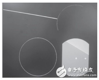
In the graph generation test, the test result graph is shown in Figure 3. The figure shows the anti-aliasing straight line, arc, circle, and the sky and the earth. A vertical character and a rotating character are displayed on the sky and the earth. It takes 984.6 μs, of which it takes 862.7 μs to read and write DDR2. When the screen refresh rate is 60 Hz, the allowable generation time for a picture is 16.7 ms, and the graphics generation meets the real-time requirements of the system.

Figure 3 Graphical test result diagram
In the process of video decoding, processing, and encoding test, the processing time of one frame of video is no more than 3 ms. There is no obvious time delay when visually observing the video output of various formats, which meets the real-time requirements of the system. In the system joint debugging, the system can output high-definition video superimposed with various high-pixel symbol graphics, the output resolution can reach 1 600×1 200, the output video field frequency can reach 60 frames·s-1, and the output video quality is high and smooth. , No obvious interference and delay.
4 ConclusionThe paper presents the overall hardware circuit design scheme of an airborne real-time video graphics processing system based on FPGA, and demonstrates in detail the hardware implementation methods of the DVI video codec module, PAL video codec module and DDR2 video buffer module in the system. The system selects a variety of new chips to build a flexible, concise and reliable hardware platform, which realizes the decoding, real-time processing and encoding output of DVI, PAL and other video formats, and has strong scalability. System test results show that the system supports a resolution of 1 600×1 200, a refresh rate of 60 frames·s-1, and smooth processing of 24-bit true color high-definition video. The processing time for 1 frame of video does not exceed 3 ms, which can be effective Increasing the processing speed of airborne video graphics has good application value.
Home Appliance Controller,Panel For Water Purifier,Control Panel For Water Purifier,Control Panel
Foshan City Jiulong Machine Co., Ltd , https://www.jlthermostat.com
