The current or voltage required to drive an electronic device to work is called the drive current or drive voltage. They can be either direct current or alternating current. Digital signals should be driven by direct current, and analog signals should be driven by alternating current.
How to test the drive current of GPIOGeneral datasheets have instructions, for example, general GPIO has 2mA, 4mA, 8mA, 16mA and other drive current settings. If you want to actually measure the size of the drive current, you can measure it by connecting a pull-down resistor in series on the GPIO. If the power domain of the GPIO is 2.8V, the GPIO drive current is 2mA, and the GPIO output is high, then the resistance of the pull-down resistor above 1.4k can stably output 2.8V, and the pull-down resistor less than 1.4k, due to the drive current Only 2mA, 2mA multiplied by the pull-down resistance is less than 2.8V, it is impossible to output 2.8V stably, the voltage will be pulled down, so it can be tested. If it is 4mA, the pull-down resistance limit is 700ohm.
How to test the actual output current of the stepper driver1. When the stepper motor is running continuously, you can see the effective value of the current in one of the phase lines with the current gear of the multimeter when the stepper motor is running continuously.
2. String a 1 ohm resistor in the phase line and use an oscilloscope to see the waveform at both ends of the resistor. The highest value on the oscilloscope is the peak current.
3. Rated current (rated current), the current marked on the electrical accessories, or the current specified by the manufacturer that the electrical accessories can carry under the specified conditions.
The rated current of electrical equipment refers to the maximum current that is allowed to pass for a long time when the heating does not exceed the allowable temperature for long-term heating under the operating conditions of the rated voltage under the reference ambient temperature. The ambient temperature has a great influence on the maximum current that can be passed for a long time. Since the ambient temperature of the equipment installation location is not necessarily the same as the reference ambient temperature, a rule is generally made: when the electrical equipment is working at an ambient temperature higher than 40 degrees Celsius (but not Above 60 degrees Celsius), for every 1 degree increase in the ambient temperature, it is recommended to reduce the rated current by 1.8%; when the working environment temperature is lower than 40 degrees, for every 1 degree decrease in the ambient temperature, it is recommended to increase the rated current by 0.5%, but the maximum should not exceed 20% of rated current. Such as: a section of 1mm2 copper core wire, rated current carrying capacity is about 11A, (30 degrees).
s8050 current drive capability test experimentPurpose: Test the current drive capability of npn transistor s8050
Equipment: resistance, breadboard, adjustable power supply with current display.
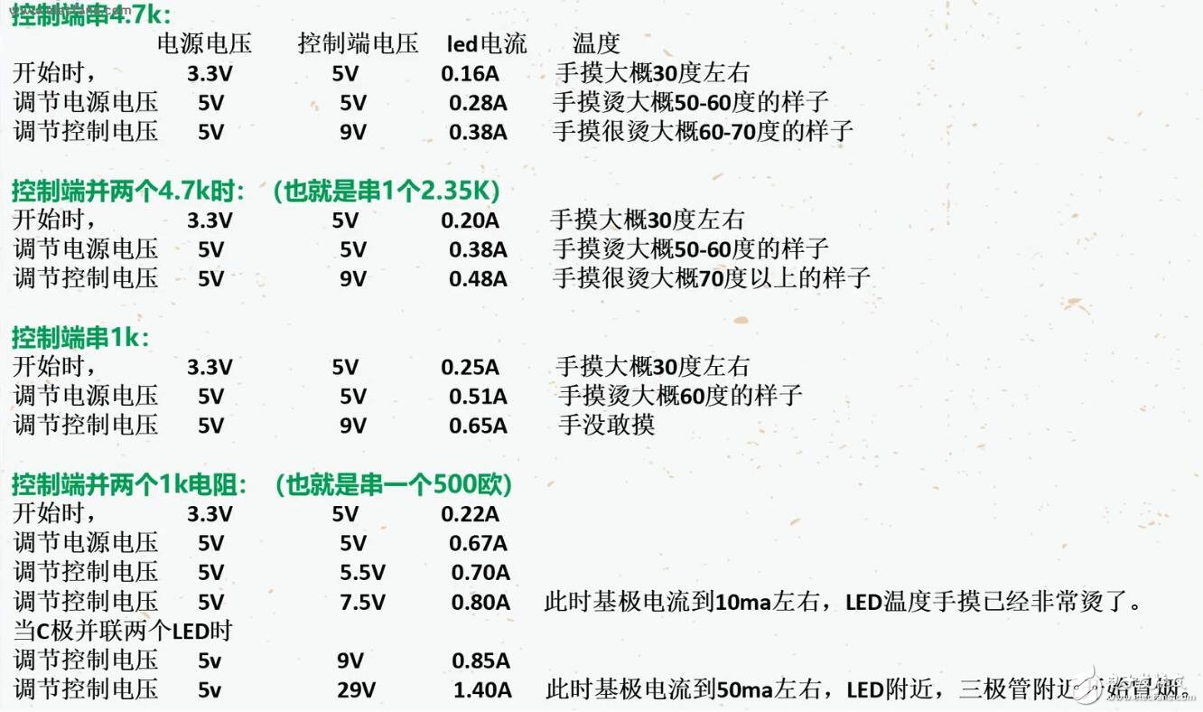
Method: The circuit is the simplest switch tube circuit, the e pole is grounded, the b pole string 4.7k resistor is connected to the control end, the control end is a 5v power supply, the 5v power supply is connected to the positive pole of the led, and the negative pole of the led is connected to the c pole of the triode. The led current is 700ma. The voltage is 3.3-3.6v (the transistor unit is bought under the floor). Use different power supply voltages, control voltages and resistors of different resistances connected in series to the base, test current and base resistance, and control voltage and power supply voltage. Between changes.

During the test, a problem was also found, temperature drift. At the beginning, the LED temperature was the same as room temperature. At this time, the control terminal was added 5v, when the power supply voltage was 3.3v, it was 0.22A, and the power supply voltage was increased. When it reaches 5V, the current increases to 0.67A. At this time, the temperature of the LED and transistor will rise sharply. After maintaining for a period of time, when the power supply voltage is adjusted back to 3.3V, the current at this time is 0.29A, which shows that the temperature will affect the LED current.
From this experiment, there are several conclusions:
1. When the transistor is turned on, there is a voltage drop between the e and c poles.
2. The smaller the resistance of the base string, the greater the base current, and within the same voltage, the greater the current between the e and c poles.
3. The control voltage can be greater than the voltage across e and c, that is to say, as long as there is current at the base electrode, there will be current at the ec electrode.
4. When the current reaches more than 600ma, the heat is already quite large.
5. When the current reaches 1.4A, the base current reaches 50ma, and the surrounding area has started to smoke. But it shows that the pipe can still reach the nominal current, but it will be very hot, so try not to use the nominal current, because it may melt the solder and cause a short circuit.
Nantong Boxin Electronic Technology Co., Ltd. , https://www.ntbosen.com
