
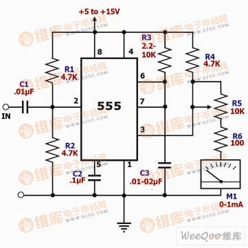
Simple frequency meter circuit
As shown in the simple frequency meter circuit diagram. In this circuit, 555 is connected to a monostable trigger mode. Whenever a low level signal is input to the second pin, pin 3 outputs a pulse signal. The width of the output pulse is determined by resistors R3 and C3. The wider the output pulse, the longer the high level signal of pin 3 is maintained. For an input signal of a specific frequency, the larger the value of R3, C3, the larger the current flowing through the meter head, and the larger the head swing. If the values ​​of R3 and C3 are constant, the higher the frequency of the input signal, the larger the current flowing through the meter, and R5 is a calibration resistor.
CCTV Power Supply,CCTV Power Supply Box,CCTV DC Distributed Power Box
Chinasky Electronics Co., Ltd. , https://www.chinacctvproducts.com