
After reset, the Program Counter (PC) points to the 00h address in order to put the device into Program/Verify mode. A 6-bit command can then be sent to the device, depending on whether the command is loaded or read, and 14-bit programming data will be provided to or read from the device. However, in the online serial programming mode, the watchdog timer circuit cannot generate a device reset.
Hardware circuit
The online serial programming circuit should pay attention to the following issues:
1) MCLR/VPP pin is isolated from the rest of the circuit
In general, the MCLR/VPP pin is connected to the RC circuit, the pull-up resistor is connected to VDD, and the capacitor is grounded. The VPP voltage must be isolated from the rest of the circuit. Depending on the size of the capacitor, the RC circuit may affect the operation of the ICSP. Therefore, when the RC circuit is connected to MCLR/VPP, a Schottky diode can be used to isolate the circuit. When programming a PICmicro ® microcontroller, the MCLR/VPP pin will be driven to approximately 13V at the same time, so the application circuit must be isolated from the programming voltage provided by the programmer.
2) Load of RB6 and RB7
The RB6 and RB7 pins are used for serial programming of PICmicro® microcontrollers. RB6 is the clock line and RB7 is the data line. RB6 is driven by the programmer. RB7 is a bidirectional pin. It is driven by the programmer during programming and is driven by the PICmicro® microcontroller during verification. These two pins must be isolated from the rest of the circuit so that they do not affect the signal during programming. The output impedance of the programmer must be considered when isolating RB6 and RB7 from the rest of the circuit. The isolation circuit must allow RB6 to be the input to the PICmicro® microcontroller, while the RB7 can be used as a bidirectional pin (which can be driven by both the PICmicro® microcontroller and the programmer).
To simplify interface design, the best way to use Microchip's recommended I/O pins is to dedicate RB6/RB7 to ICSP; these ports have extremely light loads when used as outputs; isolation circuits are used to make the signals meet ICSP specifications.
3) Capacitance problems on VDD, MCLR/VPP, RB6 and RB7 pins
The total capacitance of the programming pin will affect the rate at which the programmer's output signal rises. In a typical circuit, a few hundred microfarads of filter capacitors are typically connected between VDD and ground to suppress noise and supply voltage fluctuations. However, this type of capacitor requires the programmer to have a fairly strong driving capability to meet the VDD rise rate requirement. Most programmers can only program PICmicro® microcontrollers, not the entire application circuit. One solution is to add a driver board between the programmer and the application circuit. The driver board has an independent power supply that should meet the VPP and VDD pin voltage rise rates and power the entire application circuit. Whether RB6 and RB7 need to be buffered depends on the specific application.
4) VDD minimum and maximum operating voltage
The Microchip programming specification states that the device should be programmed at 5V. If the application circuit can only operate at 3V, then some special measures are needed. For example, the PICmicro® microcontroller is completely isolated from other application circuits during programming. Another problem is that the device must be verified at the minimum and maximum operating voltages of the application circuit. For example, in a system powered by three 1.5V batteries, the operating voltage range is 2.7V to 4.5V. The programmer must program the device at 5V and the program memory must be verified at 2.7V and 4.5V to ensure proper programming. This ensures that the PICmicro® microcontroller will operate over the full operating voltage range.
5) Oscillator for PICmicro® Microcontrollers
The PIC microcontroller waits for 1024 oscillation cycles before the code is executed. The RC oscillator does not require a power-up delay time, so the power-up delay timer is not used. The programmer must have MCLR/VPP reach the voltage required to enter programming mode before the RC oscillator oscillates 4 times. If the RC oscillator oscillates 4 or more times, the program counter will increase to an indeterminate value of X. If the device enters programming mode at this time, the program counter is not zero and the programmer will start programming the code from offset X. There are ways to compensate for the low rate of rise of MCLR/VPP. The first method is to connect the R resistor without programming the resistor of the RC oscillator. Another method is to short the PICmicro® OSC1 pin to ground with a programming interface during programming so that no oscillations occur during programming.
Considering the above situation, the ICSP connection circuit of the PIC18F4550 is implemented in the simplest way. In the circuit, a light-emitting diode driven by the RD0 and RD1 ports is added to verify whether the programming circuit can work normally.
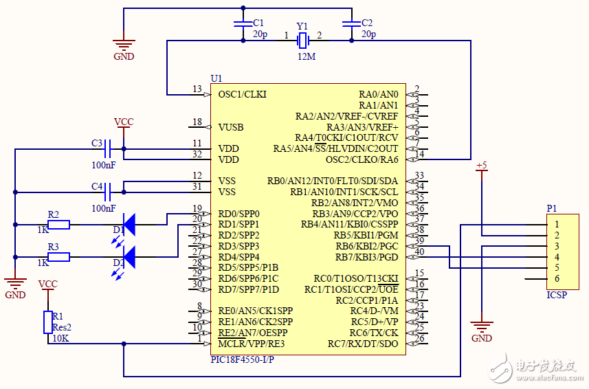
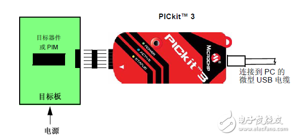
For the ICSP interface to be connected to PIKkitTM 3 as shown in the figure below, PIKkitTM 3 must be mapped to the ICSP pin.
Implementation of PIC Microcontroller Online Serial Programming (ICSP)
| About Bare Aluminium Wire |
Packaging Detailspackage can be made according to customers' requirements.
Bare aluminium
wire with high electrical resistivity, temperature coefficient of resistance is small, high operating temperature. good corrosion resistan
ce under high temperature, and particularly suitable for use in a gas containing sulfur and sulfides, low price, it is widely used in indus
trial electric furnace, household appliances, far infrared device ideal heating material.

Good performance and processing may welding nature widely used metallurgical, electrical, mechanical components and electrical
Bare Aluminum Wire,Wire Bare Chromium Aluminum,Bare Chromium Aluminum Wire,Chromium Aluminum Wire
HENAN HUAYANG ELECTRICAL TECHNOLOGY GROUP CO.,LTD , https://www.huaonwire.com