
High-availability systems, such as servers, communication gateways, and base stations, need to work continuously. Once installed on site, software upgrades are needed to enhance system functions and fix errors. Therefore, these system designs need to be able to update the system functions without interrupting their normal operation. Programmable logic devices (PLD) are often used to support in-system design updates. The improved design using PLD is lower in cost, easier to use, and stronger in performance, making programmable logic devices an ideal on-board hardware management device in these systems, which can manage on-board DC-DC converters, monitor and control the key Signal, aggregate serial communication and perform other housekeeping functions.
Indispensable PLDPLD contains a series of programmable functional units. The configuration and interconnection of these units implement specific hardware management functions on the board. Under normal circumstances, a software design tool converts a certain logic function, such as circuit board hardware management, into a configuration bit stream of a specific PLD for configuring programmable functional units and interconnects. The configuration bit stream is stored in the on-chip configuration flash memory of the programmable logic device. When the circuit board is powered on, the content in the configuration flash memory is automatically transferred to its on-chip configuration SRAM, thereby configuring the programmable function unit to perform the required hardware management tasks. The hardware management function is updated, and different bit streams can be loaded into the configuration flash memory at any time through the background without interrupting the hardware management function being performed by the programmable logic device. The configuration newly stored in the flash memory is transferred to the on-chip SRAM, and the power restart interrupts the normal operation of the system (Figure 1).

Figure 1: Most PLDs must wait for the power to restart for reconfiguration
Maintain stable output during configurationHigh availability systems cannot tolerate interruptions caused by power restarts. Since the I/O of the programmable logic device enables the DC-DC converter on the main ASIC and CPU on the board and controls the reset signal, the output of the programmable logic device must remain unchanged during the reconfiguration process. The need to keep the output stable during PLD reconfiguration poses a number of challenges for application design.
The Lattice MachXO2 or MachXO3 PLD series includes features that enable zero downtime updates (Figure 2). First, PLD performs a "background update" to load new configuration data to its configuration flash memory via JTAG, SPI or I2C. Once loaded, the "TransFR" instruction transfers the new PLD configuration from the flash memory to the configuration SRAM of the PLD. Executing the "TransFR" instruction triggers the "Keep current state" function to ensure that all I/O values ​​remain unchanged during the transmission. Finally, in the "logic initialization" step, the state machine will start to restart the power management and reset the power distribution. This will cause the power supply to shut down, forcing the board to start the power-up process.
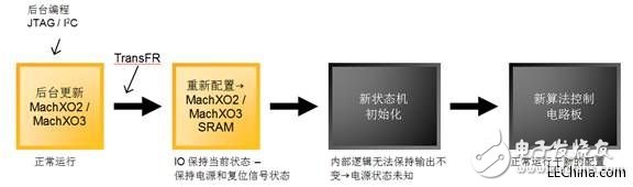
Figure 2: PLD reconfiguration steps using MachXO2/3 to update I/O without interruption
Solve problems with non-disruptive update I/OIn order to support zero-downtime updates, PLD devices must be able to maintain the output used to control power and other logic signals when the state machine created by the new image is in the initialization phase. After the new algorithms are initialized, they will gain control of the power supply and other logic signals.
In order to keep the key I/O in its original state during the initialization process, the user design needs to add "non-disruptive update I/O". As shown in Figure 3, this requires adding a latched multiplexer for each key output. The multi-way switch with latch keeps the output in the last known state during the initialization process of the state machine, and returns the output control to the state machine after the initialization process is completed. The circuit can use the "Hitless_IO_Enable" input to distinguish between normal (power-on) startup and reconfiguration, which can prevent critical output I/O values ​​from being locked during normal power-up.
discuss in depthFigure 3 illustrates the role of non-disruptive update I/O in the state machine initialization process when the new configuration is loaded into the MachXO2/XO3 device configuration SRAM.
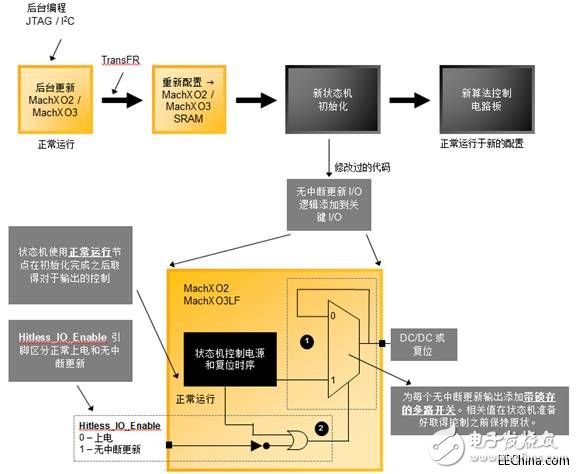
Figure 3: Non-disruptive update I/O keeps critical I/O in the last known state during initialization
Add a multiplexer with latch for each output, as long as the multiplexer control input is "0", the output will keep the current value unchanged. This means that regardless of the output state of the state machine, the DC-DC converter remains "on" (if it was previously in the "on" state). When the control signal is the logical value "1", the state of the DC-DC converter is controlled by the state machine. The state machine controls the multiplexer output through the "normal operation" node. The newly added "Hitless_IO_Enable" input of the chip can distinguish the normal "power-on" configuration (the output of the DC-DC converter is controlled during the initialization of the state machine) and the non-interrupted reconfiguration process (the DC-DC converter remains during the initialization of the state machine) constant).
Assume that the "Hitless_IO_Enable" signal that controls the non-stop update process is set to "1".
Before initialization, the state machine resets the "normal operation" signal to "0". The multiplexer with latch will ignore the output from the state machine, and the "Enable" signal of the DC-DC converter remains unchanged.
When the PLD logic is ready to resume normal operation, it sets the "normal operation" signal to the logic value "1" (high level), allowing it to gain control of the DC-DC converter. At this time, the DC-DC converter and reset of the circuit board are controlled by the updated power and reset control state machine.
actual caseThe block diagram in Figure 4 illustrates the use of PLD, which is used for CPU cluster (cluster) and platform control center (Platform Controller Hub, PCH), baseboard management controller (Baseboard Management Controller, BMC) and host bus adapter (Host Bus Adapter, HBA) and other board-level subsystems for power supply, monitoring and management. In this example, the PLD is mainly responsible for the power-on and power-off sequence of the point-of-load voltage regulator on the circuit board, and keeps the reset and control signals in a proper state when the power is restarted. During normal operation, PLD monitors the alarm parameters (temperature, voltage, memory and I/O failures, etc.) or state changes of the subsystem, and at the same time maintains the control signal stably in an appropriate state.
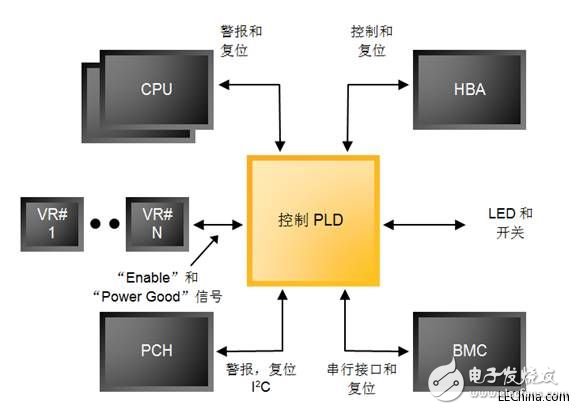
Figure 4: Control/housekeeping functions integrated in the PLD for rack-mounted servers
BMC upgrades the control PLD of the server in the background and triggers the "TransFR" instruction to run the PLD with the updated configuration. Without interruption to update the I/O, the control and reset signals or VR (voltage regulator) signals cannot remain unchanged during the initialization step. For example, if the reset signal on the CPU or its peripherals changes during the reconfiguration process, it will cause the CPU to reinitialize and start the restart process no matter what function the CPU is performing. Similarly, if the "Power Enable" signal changes, the voltage regulator or point of load power supply will be shut off, causing the device powered by the voltage regulator to enter an unknown state. This can cause the circuit board to stop running, lose or disturb data, and even cause physical damage to the circuit board's electronic components.
Adding a non-disruptive update I/O mechanism for key signals enables PLD to freeze external sensing and control signals during the reconfiguration process. In this way, the key functions of the server will not be interrupted during the routine maintenance and upgrade of the PLD. This function is also very useful for product development, which can shorten the debugging time or construct special product variables when installing the rack.
to sum upPLD can be used as a flexible and cost-effective solution to control DC converters, bridge I/O channels, and perform other board-level hardware management functions in complex electronic systems. The device supports field upgrades, which can provide manufacturers with the flexibility required to change the configuration during operation, correct design errors or add new features to the product. With the availability of non-disruptively updated I/O architectures, PLDs can now be reconfigured in an error-free and guaranteed manner. When using this architecture, the increase in the number of gates in the design is usually less than 1% and can be achieved without external components. By achieving stable and reliable configuration changes without power restart, non-disruptive update logic makes CPLD an ideal choice for hardware management solutions in networks, data center storage devices, and other task-oriented applications.
High Speed Servo Motors,High Speed Motor,Brushless Gear Motor,Brushless Geared Hub Motor
Zhejiang Synmot Electrical Technology Co., Ltd , https://www.synmot-electrical.com