Many netizens may be surprised that in the rapid development of digital chips today, 32-bit single-chip microcomputers are inexpensive and powerful, and chip cost is not the main problem of product development. Why should we popularize PIC microcontrollers, such a low-end microcontroller? The reason is very simple. Since it has not been eliminated yet, there is always a reason for its existence. The PIC microcontroller claims to have excellent stability and can work stably in a very harsh environment. Therefore, it is favored by engineers in the industrial field, and it is currently Look, any series of single-chip microcomputers are constantly innovating, product performance is also constantly improving, PIC microcontrollers are also the same, high-end PIC microcontrollers also have 32-bit, the frequency is up to hundreds of megabytes, detailed introduction can go to the official website to view.
Another reason that prompted me to write such an article is that the online introduction or learning materials about PIC microcontrollers are relatively small, not as rich as STM32 or 51 single-chip microcomputers. If there is a certain single-chip based, I want to learn PIC microcontrollers. Article, you should be able to get started.
Let me introduce the platform information and debugging tools I use.
PIC microcontroller model: dsPIC30F6014A
Development environment: MPLAB X IDE v3.05
Download tool: PIC Kit 3.5

PIC Kit 3.5 Downloader
First, install the development environment
I downloaded MPLAB X IDE v3.05 directly on the official website (), more than 400 megabytes, should be the latest version, the recommended option can be used during the installation process, and a C30 compiler (MPLAB_C30_V3.0) is also installed.
Second, new projects
When I installed the development environment, I chose the Chinese version. After entering the development environment, click: File à New Project. The following interface pops up: Select the independent project, then click Next.
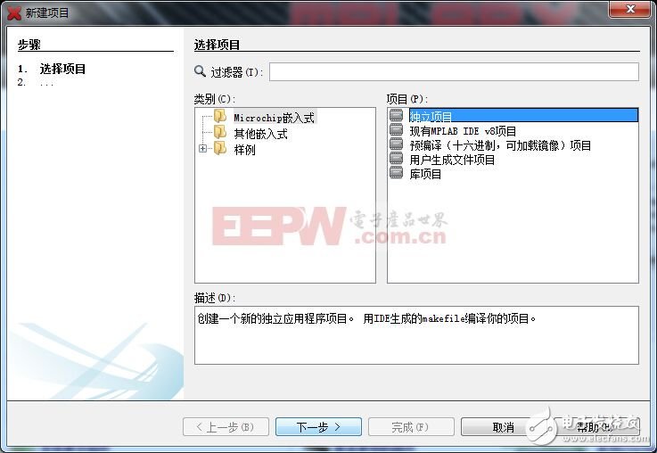
step one
Click Next and the following interface pops up: Select the MCU model you are using, here I am using the dsPIC30F6014A 16-bit MCU.
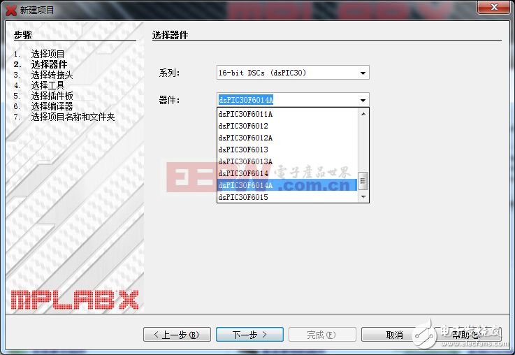
Step two
Go ahead and choose the debug/download tool here. I am using PICkit3.
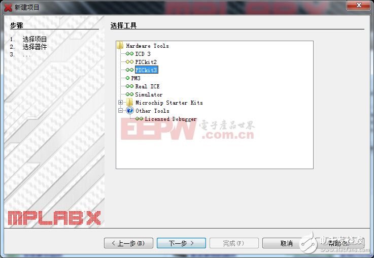
Step three
Next, this step selects the compiler and chooses the C30 compiler.

Step four
The last step is to select the save directory of the project. The code here is GB2312. The purpose of this is to make the Chinese characters in the project be recognized. Otherwise, garbled characters will appear when adding Chinese comments.
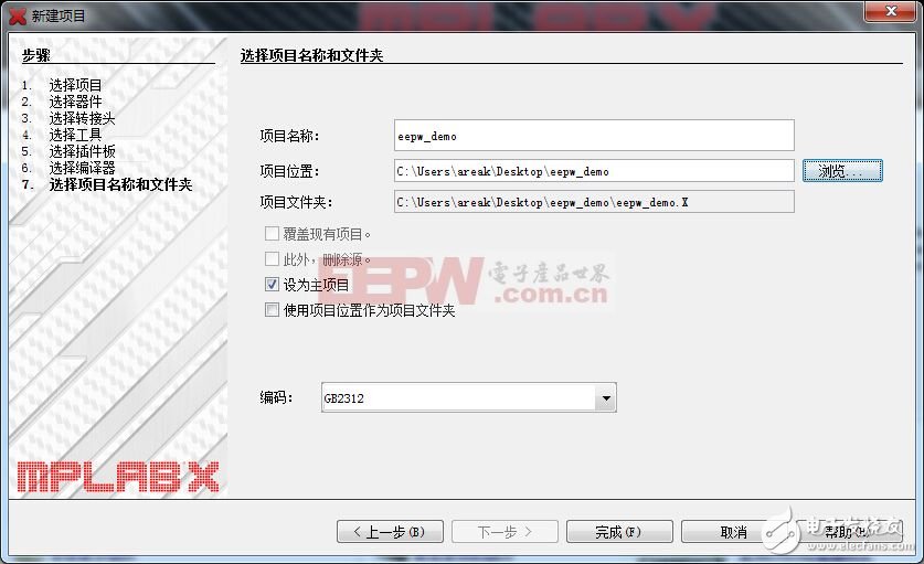
Step five
At this point, the project is newly built, the interface is as follows, in the project directory, we only need to pay attention to the header file and the source file. Right-click on the header file to add the existing header file. The source file is the same.
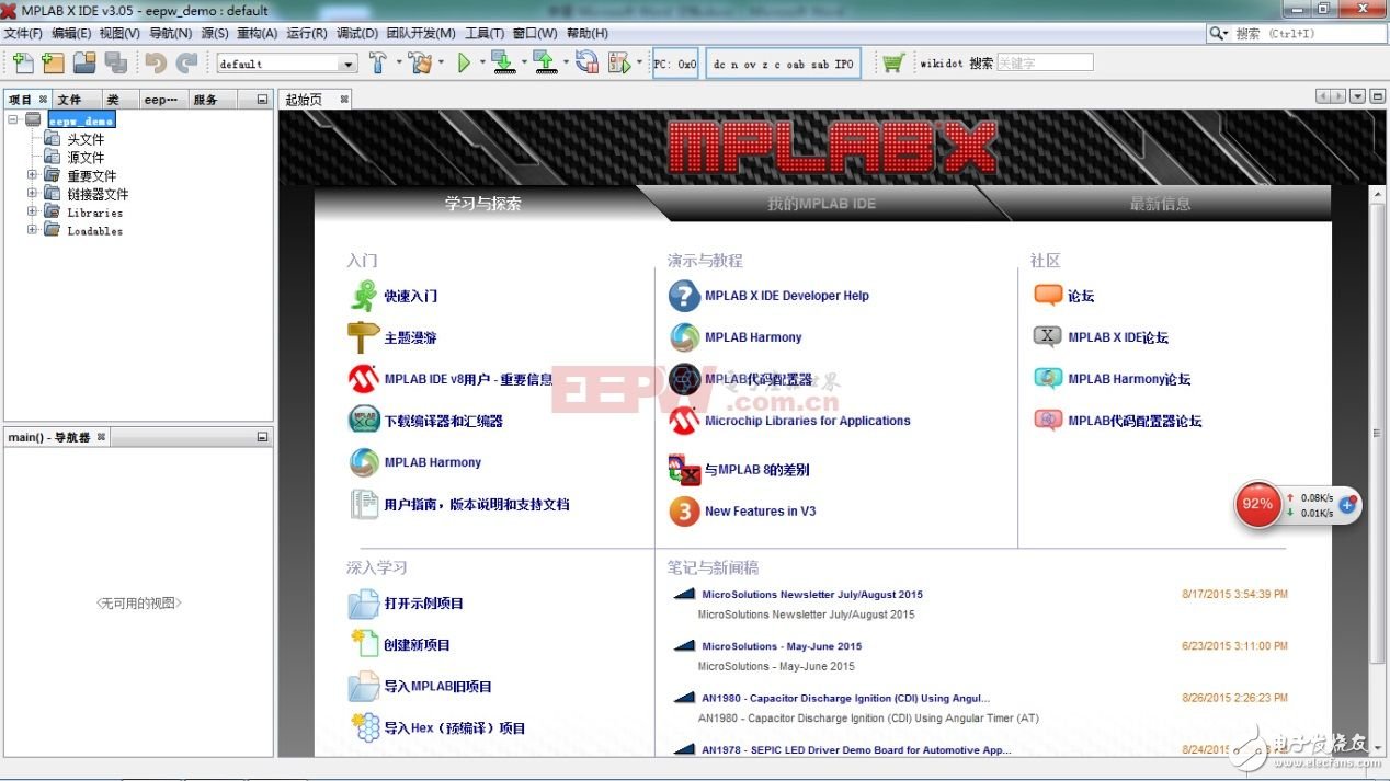
After the file is added, click the Compile button. ![]() Compile, compile and pass, it will prompt the compilation information under the environment.
Compile, compile and pass, it will prompt the compilation information under the environment.

After compiling successfully, you can download and debug online, download button ![]() Used to download the program to the inside of the microcontroller, debug button
Used to download the program to the inside of the microcontroller, debug button ![]() For online debugging procedures, note that clicking the debug button program will not be downloaded to the microcontroller.
For online debugging procedures, note that clicking the debug button program will not be downloaded to the microcontroller.
Next, use the flash test program to explain the use of this MCU. Before you come to understand the "Configuration Bit", in the development environment, click Run à Set ConfiguraTIon Bits to bring up the configuration window under the environment, under OpTIon The definition can be modified,
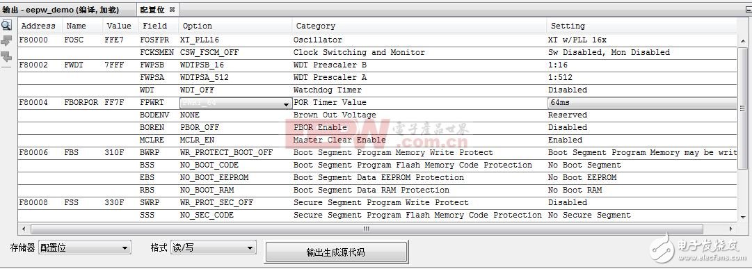
Here we talk about clock configuration and watchdog configuration, FOSC is used to configure the system clock, FWDT is used for watchdog configuration, if you want to use external crystal, internal 16 times, select XT_PLL16, if it is internal clock , 4 times the frequency, select FRC_PLL4 in the option, the same reason, the watchdog's on and off, and the settings after the opening can also be configured by FWDT, here we choose to close the watchdog, just select the WDT option as WDT_OFF can be, note, after the selection here, you must click the output to generate the source code, will automatically generate the source code, the generated source code is copied to your project file to be effective.
Please refer to the manual for some detailed configurations.

Generate code
The source code of the LED flashing light is posted below and explained step by step.
This article refers to the address: http://TIcle/279441.htm
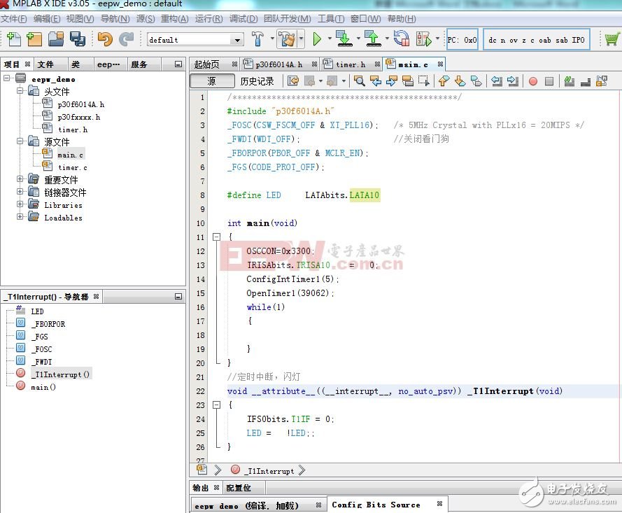
#include "p30f6014A.h" //Include header files
_FOSC(CSW_FSCM_OFF & XT_PLL16); //Configure the clock
_FWDT(WDT_OFF); //Close the watchdog
Assuming the external crystal oscillator used is 5Mhz, the system instruction cycle is calculated as:
5M*16/4=20MIPS
16 is 16 times the frequency, and it takes 4 clock cycles for each instruction to be executed. Therefore, in addition to four, the actual system clock is obtained.
IO port configuration
The IO port is very simple to use. Compared with 51, it only has one more direction control. Before using the port, set the direction first. Suppose we use the tenth bit of port A as the control bit of the LED, first set the direction of the pin,
TRISAbits.TRISA10 = 0; / / this position is zero output, set 1 input
The control port actually outputs the high and low level register bit LATAbits, and the LATA10 bit of the register is set to 0 to output high and low levels.
#define LED LATAbits.LATA10
It is worth noting that when reading the pin operation, the PORTAbits register is read instead of the LATAbits register.
We use the timing 500ms interrupt to control the LED on and off, so we need to configure the timer. Here we use the 16-bit timer TImer1. It involves two functions.
ConfigIntTimer1 (5); / / initialize timer 1, interrupt priority is 5
OpenTimer1 (39062); / / related configuration and open timer 1
Void ConfigIntTimer1(unsigned char priority)
{
IFS0bits.T1IF = 0 //Clear interrupt flag
IPC0bits.T1IP = priority; //Set the interrupt priority
IEC0bits.T1IE = 1; //Enable interrupt
}
Void OpenTimer1(unsigned int period)
{
TMR1 = 0; /* Reset Timer1 to 0x0000 */
PR1 = period; //interrupt period
T1CONbits.TCS = 0; //Select clock source
T1CONbits.TSYNC =1;
T1CONbits.TCKPS =3; //256 frequency division
T1CONbits.TGATE =0;
T1CONbits.TSIDL =0;
T1CONbits.TON = 1; //Start timer
}
Select the system clock (20MIPS) and divide by 256, 20M/256=78125, which means that the timer counts up to 78125 and takes 1 second. It takes 39062 cycles to reach 500ms, so you need to set the timing period to 39062, and because of the timing. Timer 1 is a 16-bit timer that cannot be clocked for one second. If you need to time 1s, you can use the 32-bit timer timer23 and timer45.
Timer 1 interrupt function
Void __attribute__((__interrupt__, no_auto_psv)) _T1Interrupt(void)
{
IFS0bits.T1IF = 0; / / clear interrupt flag
LED = ! LED; / / reverse the LED cycle, lighting control
}
This allows LED flashing to be achieved.
Attach the complete project source code, please download and view:
Http://forum.eepw.com.cn/thread/276018/1
There are several issues to be aware of when using this MCU:
1. Since the pin of the MCU has the function of multiplexing, when using port B, if you want to use the 7th bit of port B as the digital IO, you need to set it up. (Other ports do not need to do this.)
ADCON1bits.ADON = 0; / / turn off the AD converter
ADPCFGbits.PCFG7 = 1; / / this bit must be set, otherwise PORTB_7 can not be used as a digital IO pin
2, in the system's installation directory, comes with the use of the microcontroller's various resources, the user can refer to. My directory is: C:\Program Files (x86)\Microchip\MPLAB C30\src\peripheral_30F_24H_33F\src\ pmc (for reference)
3. When using serial port resources, you need to accurately set the serial port baud rate to set the UART1, 9600 baud rate as an example. The baud rate calculation method is: 20MIPS/((9600+1)*16)=130. Assign 130 to the U1BRG register.
4. The MCU has an internal EEPROM. If the amount of data to be stored is not large, some parameters that need to be stored in the power-down can be stored inside the MCU, which simplifies the external circuit design.
With the above foundation, I believe that learning this MCU is much easier, so that beginners can take less detours and concentrate on solving substantive problems.
CCTV Baluns,Video Balun Transceiver Transmitter,Passive Video Balun,HD CCTV Video Balun
Chinasky Electronics Co., Ltd. , https://www.chinacctvproducts.com
