The purpose of the design of the wiring system of the data center is to realize the modular structure of the system, which is simple, flexible, operable and practical. And adapt the facilities to the needs of the development of public communication network services. Experience has shown that having sufficient expansion space is essential for the installation of additional equipment and service facilities in the future. Current technology should provide a simple "plug and play" connection to add or replace modular wiring equipment, and reduce downtime and labor costs.
(1) Steps of data center wiring planning and design
When planning and designing data center construction, it is required to have an overall understanding of data center construction, and it is necessary to early and comprehensively consider the relationship and function with the building. Comprehensively consider and solve the coordination problems related to construction, electrical, electromechanical, communication, safety and other aspects in the site planning and layout.
When building or expanding a data center, the computer room wiring system needs to be coordinated with the building, electrical planning, building wiring structure, equipment layout, heating, ventilation and air conditioning, environmental safety, fire protection measures, lighting, etc., and the building needs to be fully considered. The design process and requirements of related majors require the technical clarification and cooperation of wiring technology and civil engineering.
(1) The steps of data center planning and design are recommended to be carried out according to the following process:
1) Determine the level of the computer room, clarify the functional requirements of different levels of information computer room, equipment configuration principles and the special needs of customers;
2) Evaluate the requirements of the equipment room environment temperature, humidity and equipment cooling method during long-term operation of equipment in the equipment room space. And consider the current and estimated future air-conditioning implementation plan;.
3) Provide requirements for site building net height, floor load, environmental temperature and humidity, and related construction, structure, mechanical and electrical equipment installation, safety, fire protection, electrical (such as power supply, grounding, leakage protection, lighting, environmental electromagnetic interference, etc.). At the same time. It also puts forward the basic requirements for the installation process of related equipment for the operation center, loading and unloading area, storage area, transfer area and other areas;
4) Combined with the construction of civil engineering, the preliminary plan for each functional area of ​​the data center space is given;
5) Provide the floor plan of the building, including the location and area of ​​the incoming wiring room, telecommunication room, main distribution area, horizontal distribution area, equipment distribution area and main wiring channels.
6) Provide short-term and long-term power supply methods, types and power consumption for related professional designers;
7) Reflect the installation positions and requirements of wiring and network equipment cabinets, power supply equipment and cable ducts in the plan view of the data center, and consider the setting of hot and cold aisles;
8) In the data center, combine the topological relationship between network switches, servers, storage devices, KVM equipment, etc.; transmission bandwidth, port capacity and length; the layout of cabinets and other equipment to determine the wiring system level, redundancy backup and fire retardant level , So as to formulate the overall plan of the computer room wiring system.
(2) Data center network wiring topology and cable length
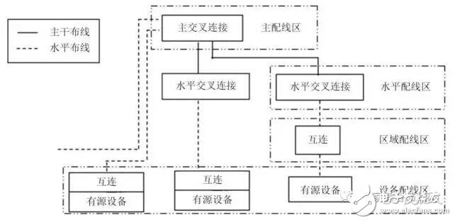
The wiring system connecting each data center space constitutes the basic elements of the star topology structure of the data center wiring system, and reflects the connection relationship between these elements. The basic elements of the data center cabling system include:
·Horizontal wiring;
· Backbone wiring;
·Equipment wiring;
Cross-connection of the main distribution area;
Cross connection of horizontal distribution area;
The regional outlet or assembly point in the regional distribution area;
· Information sockets in the equipment distribution area.

The specific network topology of the wiring system is shown in Figure 3.1.4-1.

Figure 3.1.4-1 Data center cabling system network topology structure
(2) Horizontal wiring system
The horizontal wiring adopts a star topology, and the connection port of each equipment distribution area should be connected to the horizontal distribution area or the cross-connect distribution module of the main distribution area through horizontal cables. Horizontal wiring includes horizontal cables, cross-distribution modules, equipment cables, jumpers, and regional sockets or assembly points in the regional distribution area. In the horizontal wiring system between the equipment connection port of the equipment distribution area and the horizontal cross-connect distribution module of the horizontal distribution area, there cannot be more than one assembly point of the area distribution area, and there can only be 4 channels at most Connecting devices (including the information point of the equipment distribution area, the assembly point and the two modules of horizontal cross-connection), the composition method is shown in Figure 3.1.4-2.

Figure 3.1.4-2 Horizontal wiring system channel composition (4 connection points)
In order to meet the needs of today's telecommunications services, the planning and design of the horizontal wiring system should be as convenient as possible to maintain and avoid the reinstallation of equipment in the future. It should also adapt to future equipment and service changes.
Regardless of the transmission medium used, the transmission distance of the horizontal cabling system link cannot exceed 90m, and the maximum distance of the channel cannot exceed 100m. If the data center does not have a horizontal distribution area, when the active equipment in the equipment distribution area is directly connected to the equipment in the main distribution area by optical cables, it includes the equipment optical cables in the main distribution area, optical fiber jumpers and the equipment in the equipment distribution area. The maximum transmission distance of the multi-mode optical fiber cabling channel inside should not exceed 300m (using OM4 multi-mode optical cable, the maximum transmission distance can be extended to 550m); when a 4-pair cable is used, the wiring link (not including the main wiring The maximum transmission distance of zone equipment cables, jumpers and equipment distribution zone equipment cables should not exceed 90m, and the maximum transmission distance of channels (including main distribution zone equipment cables, jumpers and equipment distribution zone equipment cables) should not exceed 100m .
If excessively long jumpers and equipment cables are used in the distribution area, the maximum distance of horizontal cables should be appropriately reduced. The total length of horizontal cables, equipment cables, and jumpers should meet the requirements of relevant regulations and transmission performance. In fact, in the data center, with the application of 40G and 100G networks, the length of the twisted-pair cable has been specified to not exceed 30m.
Based on the consideration of the influence of the compensation insertion loss on the transmission index, when the regional distribution area adopts the regional socket scheme, the channel composition of the horizontal wiring system is shown in Figure 3.1.4-3. The maximum length of equipment cables in the equipment distribution area is calculated by the following formula.

Figure 3.1.4-3 Horizontal wiring system channel (regional socket) composition
C = (102-H)/(1+D)
Z = C-T ≤ 22m, 22m is for UTP (unshielded cable) or F/UTP (shielded cable) using 24 AWG (wire gauge); if F/UTP (with 26 AWG (wire gauge) is used) Shielded cable), then Z ≤ 17m.
among them:
C is the total length of the equipment cables in the equipment distribution area and the equipment cables and jumpers in the horizontal distribution area (T+Z).
H is the length of the horizontal cable (H + C ≤100 m).
D is the degradation factor of the jumper type, 0.2 for 24 AWG UTP or 24 AWG F/UTP cable, and 0.5 for 26 AWG F/UTP cable.
Z is the longest distance between the information sockets in the regional distribution area and the cables of the equipment in the equipment distribution area.
T is the total length of the horizontal cross-connect patch cords and equipment cables.
When the regional distribution area is set up, the length of the horizontal cabling is 90m, and the channel is 100m.
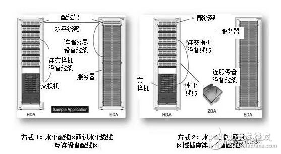
Figure 3.1.4-4 shows the two connection modes between the horizontal distribution area and the equipment distribution area.

Figure 3.1.4-4 Horizontal Subsystem Connection Mode
Point-to-point wiring connections are allowed between adjacent equipment in the equipment distribution area or in the same row of cabinets, and the length of the connecting cable should not be greater than 15m.
(3) Trunk wiring system
The backbone wiring adopts a star topology structure, which is the connection between the main distribution area, the middle distribution area, the horizontal distribution area, the incoming line and the telecommunications room. The backbone wiring includes backbone cables, main cross-connect, intermediate cross-connect and horizontal cross-connect distribution modules, equipment cables and jumpers. The channel composition of the backbone cabling system is shown in Figure 3.1.4-5.

Figure 3.1.4.-5 Channel composition of backbone cabling system
(1) The backbone wiring design should also be able to adapt to the growth of business requirements and changes in system facilities during each use period. When the horizontal cross-connection distribution module of each horizontal distribution area is directly connected to the main cross-connection distribution module of the main distribution area or the middle cross-connection distribution module of the intermediate distribution area, it is not allowed to be in the cable routing There is a cross connection.
(2) Allow the horizontal distribution area (HDA) to be interconnected by backbone cables. This interconnection is a non-star topology and serves as redundancy for the backbone connection route between the main distribution area and the horizontal distribution area. Backup, or to avoid the problem of excessive distance when supporting some old applications.
(3) In order to prevent the incoming circuit from exceeding the limit of the maximum length requirement, it is allowed to set up interconnection routing between the horizontal cross-connection and the secondary incoming line.
The longest transmission distance supported by the backbone cable is related to the network application and the transmission medium used. The total length of the backbone cable, equipment cables, and jumpers should meet the requirements of related regulations and transmission performance. In order to shorten the transmission distance of the cable in the wiring system, the main cross-connect is generally set in the middle of the data center. Wiring systems that exceed these distance limits can increase the intermediate distribution area or split it into multiple computer room partitions. The length of the backbone cable in each partition should be able to meet the requirements of the standard. Inter-section interconnection does not belong to the scope of this article. You can refer to the application of cabling system cable connections in wide area networks.
2. Layout of the machine roomThe layout of equipment in the computer room mainly faces that the air distribution of the air conditioner in the computer room is not blocked, and the various pipe routes in the computer room do not overlap. The reinforced base of the cabinet is easy to install, and the cabinet can be grounded nearby. This needs to be integrated in the design. consider.
(1) Cabinet/rack cooling settings
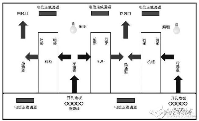
The placement of cabinets, racks, and cable routing channels is very important for the airflow organization design of the computer room. Figure 3.1.5 shows the recommended installation locations for various devices.

Figure 3.1.5 Equipment placement and airflow organization in the computer room
In the past, the communication room and the information room used the "face-to-back" arrangement of machine columns, and did not pay much attention to the influence of the placement of the cabinet on the airflow organization, because the heat generation of a cabinet at that time reached about 1.5KW. Now, the equipment cabinets are arranged in an alternating pattern, that is, the cabinets/racks are arranged "face to face" to form a hot aisle and a cold aisle. The cold aisle is the front area of ​​the rack/cabinet, and the hot aisle is located at the rear of the rack/cabinet, forming a cooling route from front to back. The equipment cabinets are arranged on both sides of the cold aisle. The air-conditioning is blown out from the air outlets of the raised floor. The equipment cabinets on both sides of the hot aisle are back to back. The floor of the hot aisle is non-porous, and the hot air is discharged by the return air vent on the ceiling.
(1) Adopt the way of wiring under the floor
1) Power cables and data cables are distributed under the floor of the hot aisle or cabinet/rack and laid in layers. If it is necessary to route the wires under the floor of the cold aisle, the height of the electrostatic floor should be increased accordingly to ensure that the cooling air flow is not affected.
2) In order to improve the clear space under the raised floor, the bridge frame of the communication cable can also be set on the top of the cabinet. It not only facilitates the laying and introduction of cables into the cabinet, but also prevents interference from electric and magnetic fields of power cables. At present, this kind of arrangement is more common.
3) Cable openings should be opened on the floor according to actual use. Adjusting gates, shock absorbers or brushes can be installed at the openings to block the airflow to prevent the loss of cold air. In a cabinet that is not fully equipped with equipment, it is recommended to use blank baffles to prevent the "hot aisle" airflow from entering the "cold aisle", causing circuitous airflow. For moderate heat load, the cabinet can adopt any of the following ventilation measures:
· Through the openings or holes on the front and rear doors, provide more than 50% open space, increasing the size and area of ​​the ventilation opening can improve the ventilation effect;
· Fans are used to promote airflow through the vents on the door and the sufficient space between the equipment and the rack door. When installing the cabinet fan, it is required not only to not destroy the performance of the hot and cold aisle, but also to increase its performance. The airflow from the fan must be sufficient to dissipate the heat emitted by the cabinet. Where the thermal efficiency of the data center is the highest, the fan requires power supply from a separate circuit to avoid interrupting the normal operation of communication equipment and computer equipment when the fan is damaged.
· For high heat loads, natural airflow is not efficient, and forced airflow is required to provide sufficient cooling for all equipment in the cabinet. The forced air flow system adopts a cold and hot aisle system with additional vents.
(2) Pedestrian passage setting, the distance between the pedestrian passage in the host room and the equipment should meet the following requirements:
1) The clear width of the passage used for transportation equipment should not be less than 1.5m;
2) The distance between the front of the cabinets or racks arranged face to face should not be less than 1.2m;
3) The distance between the back of the cabinets or racks arranged back to back should not be less than 1m;
4) When it is necessary to repair and test on the side of the cabinet, the distance between the cabinet and the cabinet, and between the cabinet and the wall should not be less than 1.2m;
5) When the length of cabinets arranged in rows exceeds 6m (or the number exceeds 10), there should be aisles at both ends; when the distance between the two aisles exceeds 15m (or the number of cabinets in the middle exceeds 25), between them The walkway should also be increased; the width of the walkway should not be less than 1m, and the width of the walkway can be 0.8m.
In the project, the distance between the passages between the machine rows should also take into account the actual size of the raised floor panels, and try to round the reserved passages according to the size of the panels, which is conducive to the installation of the seismic base of the cabinet and the opening of the panels.
Note: The full text is extracted from the book "Application Technology of Data Center Integrated Cabling System". The book was written by Mr. Zhang Yi, the deputy secretary-general of the Engineering Intelligent Design Branch of the China Survey and Design Association, along with various companies in the wiring industry and front-line professionals. From the background of the development of integrated wiring to the current market situation, with the integrated wiring system of the data center as the center, the important links of the wiring structure frame design, cable selection, construction and so on are all classified and explained in detail.
Wired Barcode Scanner,Wired Scanner,Wired 2D Barcode Scanner,Barcode Scanner Usb Cable
ShengXiaoBang(GZ) Material Union Technology Co.Ltd , http://www.sxbgz.com
