
Vehicle automatic transmission is an important part of automotive electronic control technology. The use of computer and power electronic drive technology to achieve automatic vehicle transmission can eliminate the difference in driver's shifting technology, reduce the driver's labor intensity, improve driving safety, and improve the power and economy of the vehicle. The continuously variable transmission system of an automobile is generally composed of a continuously variable transmission CVT (ConT Inuously Variable Transmission) and a continuously variable transmission controller TCU (Transmission Control Unit).
1 The basic structure of CVT
The continuously variable transmission system of automobiles mainly has the following forms: (1) AT-HMT (Hydrodynamic Mechanical Transmission) is widely used in cars, buses, heavy vehicles, commercial vehicles and engineering vehicles. (2) Mechanical AT-AMT (Automa ted Mechanical Transmission) is composed of an ordinary mechanical transmission and a microcomputer-controlled electro-hydraulic servo-operated automatic shift mechanism. It is currently used in some low-end cars, local trucks, and commercial vehicles. (3) Stepless AT-CVT (ConT Inuously Variable Transmission) is one of the most used in small displacement cars. Its main structure and working principle are shown in Figure 1.
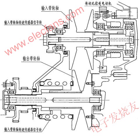
Figure 1 Main structure and working principle of stepless AT-CVT
The development of CVT technology has a history of more than 100 years. The German Mercedes-Benz company is the originator of CVT technology in cars. As early as 1886, the V-rubber belt CVT was installed on the gasoline engine cars produced by the company. However, due to structural design and material selection issues, the transmission mechanism is too large and the transmission ratio is too small to meet the requirements of the car. These shortcomings limit its application. Until 1979, through the improvement of structure and the use of special steel belts, the transmission ratio of CVT was significantly improved, and it had the prerequisites for wide application in vehicles. Since then, vehicles of Ford, Fiat and Nissan have used this type of transmission mechanism.
The V-shaped thrust steel strip used by CVT is composed of multiple wedge-shaped steel plates installed on flexible maraging steel rings. Its power is input from the driving wheel, passes through the V-shaped steel belt, and is output by the driven wheel. The pulley consists of two parts that can slide relatively. The steel strip is located in the groove between the two parts. When the two parts of the pulley are close together, the groove is narrow, and the steel belt is located on the outer edge of the pulley. At this time, the working diameter of the pulley is the largest. With the relative sliding between the two parts, the groove becomes wider and wider, and the steel belt gradually approaches the center of the pulley, that is, the place with the smallest working diameter. When the car has just started and the speed is low, the working diameter of the driving wheel is small, and the transmission can get a large transmission ratio, so that the car has enough power to overcome the running resistance. As the vehicle speed increases, the working diameter of the driving wheel gradually increases, the working diameter of the driven wheel becomes smaller and smaller, and the transmission ratio of the transmission also decreases accordingly. Because the working diameter of the pulley can be continuously changed, the transmission ratio of this transmission is also stepless and continuously variable, and the transmission of power is more stable. Its power and economy are much higher than that of a planetary gear automatic transmission. In the actual operation of the car, the control of the transmission gear ratio is automatically completed by the TCU controlling the DC motor.
2 Basic structure of TCU
The basic structure of TCU is shown in Figure 2. It consists of a single-chip microcomputer, a detection circuit, a drive circuit, a power supply circuit, and a communication circuit.
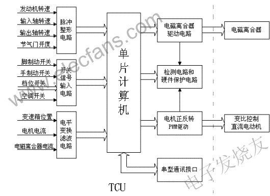
Figure 2 Basic structure of TCU
The single chip microcomputer adopts the single chip PIC18F452 launched by the American Microchip company in March 2002. It can meet the requirements of TCU in function, it has low power consumption, wide operating temperature range in performance, and can work normally at lower voltage , Especially suitable for automotive appliances. The detection circuit is divided into pulse detection, switch detection and analog detection. Pulse detection is divided into pulse counting and pulse width detection. For example, the measurement of starting speed, input and output shaft speed adopts pulse counting method. Throttle opening is measured by pulse width.
The measurement of analog quantity is mainly composed of filter circuit and amplifier circuit. The A / D conversion adopts the 10-bit A / D converter included in the microcontroller. The variable ratio control of the gearbox is driven by a DC motor. In the TCU, an H-type circuit composed of 4 MOSFETs realizes positive and negative PWM control of the motor. The current of the electromagnetic clutch is also driven by the MOSFET. In addition to the main switching element and freewheeling diode, there are protection circuits and current detection circuits in the drive circuit.
The function of the communication interface is mainly to observe the working state of the TCU, analyze the fault of the detection sensor and share the sensor resources.
3 TCU control system program block diagram
The main program block diagram of the TCU control system is shown in Figure 3. The program first allocates the internal RAM, and then initializes each functional module such as Administrator / D converter, timer, and PWM waveform generator. The transmission ratio of the gearbox should be at the position of the smallest ratio every time, so the gearbox should be returned to the position every time you stop. After starting the car, first check various parameters, such as gear switch, engine speed, throttle opening Degrees, gearbox input, output shaft speed, etc. These parameters are the basis for controlling the electromagnetic clutch current and motor state. When it is necessary to increase the transmission gear ratio, the TCU controls the motor to rotate forward, otherwise it controls the motor to reverse. The electromagnetic clutch control adopts the current incremental control method. Its control is good or bad, which directly affects the stability and economy of car operation.

Figure 3 TCU control system main program block diagram
4 Operation result
Figures 4 and 5 show the relationship between the electromagnetic clutch current and gearbox transformation ratio when the car is actually running. Among them, Figure 4 is a graph of the electromagnetic clutch current and engine speed, throttle opening and input shaft speed when the vehicle speed is accelerated from zero to 120KM / H, and after 120KM / H, the throttle is decelerated to zero. It can be seen from the figure that the throttle valve is added to the maximum for a period of time, and the electromagnetic clutch current is synchronously followed by the increase. When it is added to the peak value, it continues to remain unchanged, and the engine speed is also added to a value to remain unchanged. It can also be seen that the electromagnetic clutch current is constantly shaking during the increase. It can be seen that the electromagnetic clutch is continuously slipping during the rise. During this period of time, the engine speed is not proportional to the input shaft speed until the electromagnetic clutch reaches a stable Only maintain a certain proportional relationship after the value. When the throttle is fully released, the electromagnetic clutch current will then drop to a small value and remain unchanged until the vehicle speed reaches the gearbox gear shift, the electromagnetic clutch current continues to decrease, when the vehicle speed is zero, The electromagnetic clutch current is then reduced to zero. It can be seen from Figure 4 that when the vehicle speed is increased from zero to 120KM / H, the electromagnetic clutch current is zero, and the input shaft speed is also slowly reduced to zero. Throughout the process, we can see that the throttle opening rate of change represents the driver ’s intention, and the electromagnetic clutch current is mainly determined by the throttle opening. The degree of slip of the electromagnetic clutch determines the transmission proportional relationship between the engine speed and the input shaft speed.

Note: dark blue—input shaft speed, yellow—throttle opening, purple-red—engine speed, light blue—electromagnetic clutch current
Figure 4 Electromagnetic clutch current relationship curve when the motor accelerates
Figure 5 shows the relationship between the position sensor and the input shaft speed, output shaft speed and motor voltage when the vehicle speed is increased from zero to 120KM / H and then reduced from 120KM / H to zero. It can be seen from the figure that when the speed of the car is increased from zero to 120KM / H, the position sensor ratio is reduced from the maximum to the minimum, and the corresponding motor is reversed. When the vehicle speed starts to decrease from 120KM / H, the position sensor will remain unchanged. At this time, the motor does not rotate, and the input shaft speed and output speed decrease proportionally. When the vehicle speed reaches a certain value, the position sensor speed ratio starts to increase from the minimum until It is the maximum value, and the motor is reversed at this time (because the current sensor used in the test is unidirectional, so the reverse current is not reflected in the figure). The input shaft speed and output shaft speed drop disproportionately to zero. It can be seen from Fig. 5 that when the vehicle speed is increasing, the test value of the speed ratio of the position sensor continuously decreases (the corresponding speed ratio increases). Conversely, when the vehicle speed is decreasing, the test value increases when the vehicle speed is less than a certain value. Thus, the automatic adjustment of the transmission ratio is realized.

Note: yellow—position sensor, dark blue—input shaft speed, purple-red—output shaft speed, light blue—motor voltage
Figure 5 Gearbox ratio when the car decelerates-speed curve
It can be seen from the operation results that the designed TCU can realize the automatic control of the electromagnetic clutch torque and the transmission ratio. From the perspective of actual operation, the process of starting and stopping and acceleration and deceleration is smooth. And it has better economy.
Photovoltaic New Energy Magnetic Ring Inductor
Photovoltaic New Energy Magnetic Ring Inductor,Common Mode Toroidal Inductors,High Frequency High Power Inductors,Three-Phase Common Mode Filter Inductor
Shenzhen Sichuangge Magneto-electric Co. , Ltd , https://www.scginductor.com