Design of Ethernet application system with embedded USB
With the rapid development of USB technology, people have higher and higher expectations for USB. Although the status of USB technology in the field of desktop computers has been solid, but due to its host-centric topology, any USB data transmission must be initiated and controlled by the host, and all USB devices can only be established with the host. connection. Not only that, software complexity and high power requirements have increased interest in using USB in embedded devices. Embedded USB combined with Ethernet technology can convert USB devices to TCP / IP, so that USB devices are no longer restricted by distance, can access USB devices anytime and anywhere through the network, and can allow one USB device to be used by multiple users, thereby improving USB devices Utilization rate. By enabling USB devices to have network-capable device networking servers, USB storage, USB video, and USB printing can be used for networking. This paper presents a method of using ARM7 to implement embedded USB, and combined with Ethernet application technology, makes it easy to access USB devices through the network.
1 System composition and working principle
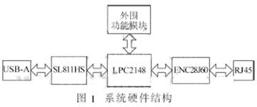
The system hardware structure is shown in Figure 1. The system uses LPC2148 to control the embedded SL811HS and ENC28J60, which realizes the connection between the USB device and Ethernet, which facilitates the network sharing of USB devices and the long-distance transmission of data. SL811HS mainly realizes the function of USB HOST, it can recognize USB devices, and can read and write operations to the device. ENC28J60 mainly completes the network communication of the system and realizes the remote access to the USB device of the system. 
2 System module design
LPC2148 is a 16 / 32-bit ARM7TDMI-STM CPU microcontroller that supports real-time simulation and tracking, and has a 512KB embedded high-speed on-chip FLASH memory. The on-chip 128-bit width memory interface and unique acceleration structure enable 32-bit code to run at the maximum clock frequency. Applications that have strict control over code size can use 16-bit Thumb mode to reduce code by more than 30% while sacrificing performance. The LPC2148 has a smaller 64-pin package and can use up to 46 GPIOs. Its extremely low power consumption, multiple 32-bit timers, multiple 10-bit ADCs, one DAC, and rich interfaces make it particularly suitable for various types of applications such as industrial control, medical systems, and access control embedded MODEM. The reason for choosing LPC2148 is that it integrates FLASH, RAM, SPI interface on-chip, making the peripheral circuit simple and cost-effective.
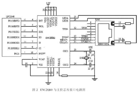
ENC28J60 is the world's first 28-pin independent Ethernet controller launched by American Microchip Technology Corporation in 2005. It can provide a low-pin-count, low-cost, efficient and easy-to-use remote communication solution for embedded applications. In addition, the ENC28J60 Ethernet controller uses the industry-standard SPI serial interface, and only a few wires are needed to connect with the main control chip, as shown in Figure 2. CS and RESET are connected to the main control chip to make the software design more flexible. 
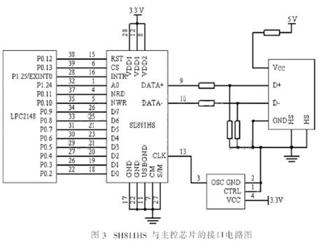
SL811HS is an embedded USB host device controller designed by Cypress. It is widely used in embedded systems. It can select the master-slave mode through software control, support low-speed and full-speed transmission and automatically detect low-speed or full-speed devices. A0 distinguishes addresses and Data, and support address increment mode. The interface circuit between SL811HS and the main control chip is shown in Figure 3. 
3 Software design
The system software is mainly composed of embedded TCP / IP program and embedded USB. The system program performs corresponding processing according to the type of Ethernet data packet received to complete a specific function. For example, browse and modify local data through Ethernet remote login to achieve the purpose of local data network sharing.
3.1 Embedded TCP / IP implementation
Embedded TCP / IP implementation includes Ethernet controller ENC28J60 bottom driver, TCP / IP protocol. ENC28J60 can be directly connected to the SPI interface on many host controllers. This device only supports SPI 0,0 mode. In addition, the SPI port requires SCK to be low when in idle state, and does not support clock polarity selection. Data is shifted in on each rising edge of SCK, and commands and data are sent to the device through the SI pin. ENC28J60 outputs data from the SO pin on the falling edge of SCK. The CS pin must remain low when performing an operation, and return to high when the operation is complete.
3.1.1 ENC28J60 bottom drive
Before using ENC28J60 to send and receive data packets, the device must be initialized. Depending on the application, some configuration options may need to be changed. Normally the initialization task will be completed immediately after reset, and no longer need to be changed. The initialization tasks mainly include: (1) Initialize the receive buffer: Before receiving the data packet, the ERXST and ERXND pointers must be programmed to initialize the receive buffer. The storage space between ERXST and ERXND is exclusively for receiving hardware. (2) Initialize the transmit buffer: All storage space that is not used as the receive buffer will be used as the transmit buffer, so no special initialization of the transmit buffer is required. (3) Wait for OST: If the initialization is performed immediately after power-on reset, the ESTAT.CLKRDY bit should be queried to ensure that sufficient time has passed before starting to modify the MAC and PHY registers. (4) PHY initialization: PHY registers cannot be accessed directly through the SPI control interface, but are done through a set of special MAC control registers with MIIM. In the program, the PHY write function is used when configuring the LED. When writing the PHY register, first write the address of the PHY register to MIREGADR, and then write the contents of the high and low 8 bits to MIWRH and MIWRL respectively.
When sending a data packet, ENC28J60 will automatically generate a preamble and a frame start delimiter. In addition, the MAC can also automatically generate padding and CRC fields according to the configuration. The main controller generates all other frame fields and writes them to the buffer to be sent. In addition, ENC28J60 also requires that a control byte of a packet be added before the data packet to be sent. When receiving data packets, you can use the interrupt method or the query method. Because this design does not have high requirements for real-time performance, the query method is adopted. If a data packet arrives, ENC28J60 will set the PTKIF bit of the EIR register. This bit is continually queried while the program is running to determine whether a data packet has arrived.
3.1.2 Ethernet packet processing
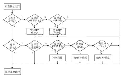
Network protocols are usually developed on different protocol layers, and each layer is responsible for different communication functions. The TCP / IP protocol is a combination of multiple protocols at different levels. When the system receives the Ethernet data, the data begins to strip from the protocol by the data link layer layer by layer the header added by each layer of the protocol. The main program is compiled according to the idea of ​​Ethernet data frame sharing. The program framework is shown in Figure 4. 
3.2 Embedded USB implementation
The embedded USB software is mainly divided into 4 parts: SL811HS initialization, USB device identification and configuration, mass storage protocol and FAT file system. SL811HS has a total of 16 configuration registers, of which 00-04H, 08H-0CH are the working configuration registers of USB-A and USB-B, 05H is the control register 1, 06H is the interrupt enable register, all bits of 07H are reserved bits, 0DH For the status register, 0EH is the SOF count register, 0FH is the high bit of the SOF count register and control register 2. After the SL811HS powers up and starts working, first set the third bit of register 05H to 1, clear it after a delay of 30 ms, and then reset the USB bus; then write 61H in the 06H register to enable the device to detect the interrupt.
When a device is inserted, the D + pin of SL811HS will be set high. The 7th bit of register 0DH of SL811HS is set to 1 and an interrupt will be generated. The system will recognize that a USB device is inserted and the USB device can be configured. Through the standard device request functions ClearFeaure (), GetConfiguraTIon (), GetDescriptor (), SetAddress () and other functions to complete the configuration of the device.
The system can detect the status of the U disk (such as access, unplug), access to the U disk through the network, including creating files, directories, and reading and writing files, etc., to achieve the purpose of USB device network sharing. However, because the drivers of different USB devices are usually different, it is impossible for USB as an embedded application to install all the drivers like a PC operating system. However, with the development of embedded technology, you can use the network update driver. As long as a certain USB device is connected, you can update the firmware of the system to achieve the purpose of identifying the device and using the device. This is also where the system is currently in need of improvement.
planar magnetics transformer,High Frequency T 200W Planar Transformer,flyback planar transformer,coilcraft planar transformer
IHUA INDUSTRIES CO.,LTD. , https://www.ihua-magnetics.com
