In order to save the microprocessor pins, another method that can be adopted is to realize the monitoring and control line and microprocessor communication through the glue logic interface. With this method, fewer wires are connected to the microprocessor pins. Developing such a system is cumbersome and time-consuming because it requires more devices, more connection lines, or more complex code development.
This article presents a good solution for monitoring and controlling several peripheral signals, which provides a simple and economical method for accessing the parallel bus and provides a convenient way to interface with different electronic devices. This scheme is based on the standard PCF8574 and PCF8574A devices. The I2C addresses of these devices are different. These two devices are used as expanders here.
This expander has a 2-wire I2C communication bus that interfaces with the I2C host for bidirectional data transmission. The I2C bus consists of two signal lines and one ground line. The signal lines are bidirectional serial data (SDA) lines and bidirectional serial clock (SCL) lines (see Figure 1). The SDA and SCL lines are connected to the positive supply voltage via pull-up resistors. When the bus is idle, these two signal lines are pulled high.

Figure 1 I2C-bus device connected to the I2C bus via bidirectional SDA and SCL lines
Each device connected to the I2C bus has its own dedicated address based on its function, and each device can act as a receiver or transmitter. The configurable expander has a dedicated 7-bit address. The first 4 bits of the PCF8574 7-bit address are 0100, while the PCF8574A is 0111. The lower 3-bit address is set by the device pins A2, A1, A0. Therefore, the device's complete, dedicated address is set by A2, A1, and A0. Table 1 shows the various possible settings for the PCF8574 and PCF8574A specific addresses.
This ability to set a dedicated address for the device allows up to eight PCF8574 and eight PCF8574A devices on the same I2C bus. Because each device has 8 I/O pins, using the PCF8574 and PCF8574A allows a single I2C bus to control up to 128 I/Os.
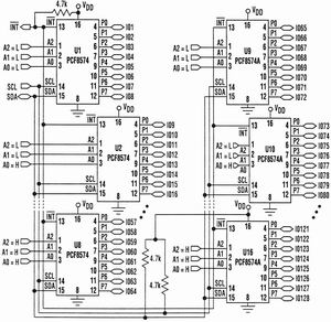
The communication between I2C and expander is initialized by the host, and the host sends the address bits of the slave device communicating with the host. The first part of the address byte consists of a 4-bit address code, which is set to 0100 for the PCF8574 device and 0111 for the PCF8574A device. Chip select bits (A2, A1, A0) follow the address code. This allows up to 8 PCF8574 and 8 PCF8574A to be used on one bus and can determine which device to access. For the responding device, the chip select bits in the address byte must correspond to the logic levels on the corresponding A2, A1, and A0 pins. The circuit shown in Figure 2 uses 8 PCF8574 and 8 PCF8574A devices to control and monitor up to 128 I/Os.

Figure 2 I/O expansion circuit implemented with PCF8574 and PCF8574A
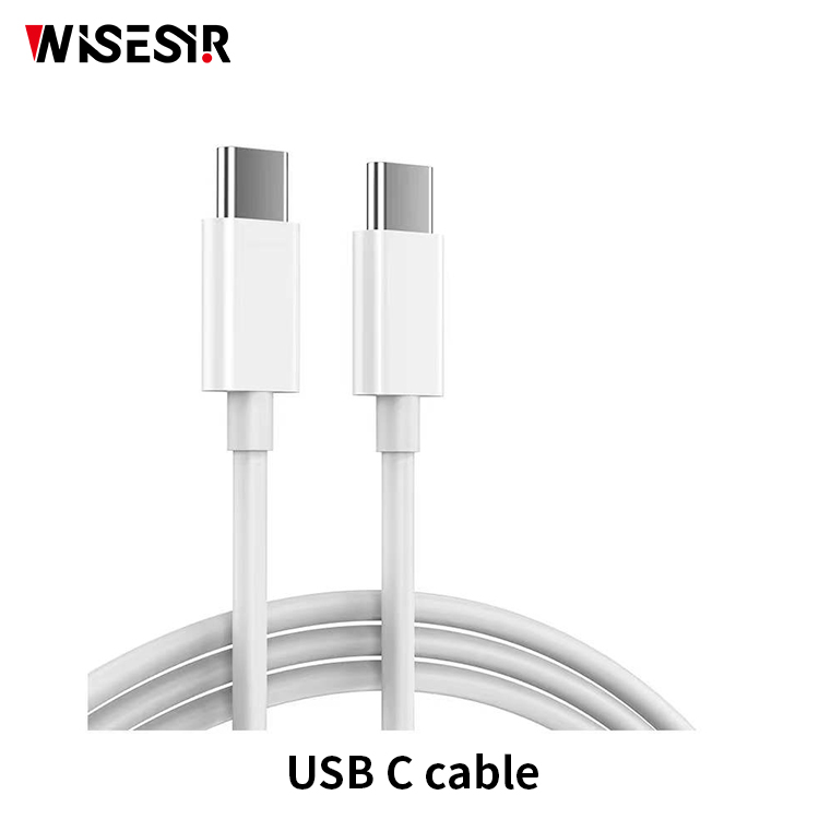
USB C Cable
A USB-C cable is a recent type of USB connector that's easier to use and more powerful than older USB types. USB-C cables can be used to quickly charge many popular devices, including the MacBook Pro and Nintendo Switch, and transfer data faster than any other USB type.

6 In 1 Charging Sets,5A Fast Charging Data Cable,Charging Data Cable,Fast Charging Data Cable
Pogo Technology International Ltd , https://www.pogomedical.com
