The target simulation system studies the optical characteristics of various target reflection-coded lasers received at the entrance of the seeker in the battlefield environment in real time and accurately. Specifically, the laser energy and spot size changes are controlled in real time under the control of the computer and the motor controller, and the laser target characteristics, energy variation characteristics and spot size variation characteristics of the laser bomb seeker inlet are simulated. . This precise simulation requires real-time acquisition and processing of the position information and speed information of the target. The program-controlled integrated laser based on the stepper motor servo drive system can not meet the real-time requirements of the system. Therefore, the author designed a motion control system based on servo motor and motion control card. The system has a significant improvement over the previous system in controlling the real-time variation of laser spot size and energy.
Real-time design of motion control
The real-time control of the size and energy of the laser spot is a real-time design of the variable attenuation system and the controllable beam expansion system in the programmable integrated laser, which is a key to the design of the target simulation system. In the design, we carried out a digital simulation with a certain type of laser guided weapon as the background, and obtained a typical digital simulation energy attenuation (corresponding to the motor control step data) curve as shown in Figure 1-2.
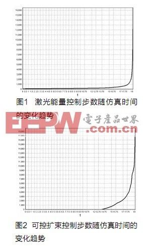
As can be seen from the above data and graphs, energy and spot changes are slower during most of the initial bombing and flight, and dramatic changes occur as they approach the target. This shows that the laser energy and the size of the spot seen by the seeker change over time when the bomb approaches the target is not a linear relationship. In view of this, the system is designed with full consideration of the real-time tracking range of spot size and energy, and considering the possibility of engineering realization, the TSA50 standard high-speed electronically controlled translation stage is selected. The rotary table is directly realized by using a hollow torque motor to drive the rotating prism. In particular, the system changes the translation stage and the rotary table driven by the stepping motor to be driven by the servo motor. The main consideration is that the servo motor has a short starting time and a high speed, and can drive the laser to be installed in a very short time. The translating prism and the rotating prism perform high-speed motion to simulate the size and energy of the spot that is sensitive to the proximity of the seeker, thereby meeting the requirements for real-time changes of the spot. The high-speed translation stage and the rotating electric machine respectively drive the eyepiece of the beam expander system and the Gem-Fuck prism's analyzer, so that the energy and spot change can fully meet the real-time control requirements when the projectile distance is >300m. In the remaining time, the motor makes full speed motion to approximate the steep change of the last stage.
Based on the above objectives and the design of motion control functions, the use of dedicated motion control chips is a better choice [2]. The dedicated control chip communicates with the CPU of the PC through the PCI bus, receives the control command of the PC, performs calculation and pulse transmission by the internal logic circuit, and detects the status of some switch signals (such as limit signals) and reports to the PC. To achieve the function of motion control. In this scenario, all motion control details are done by dedicated chips on the motion control card, eliminating the need to take up resources from the PC. The PC can focus on user interface processing and monitoring of motion control card status. The motion control dedicated chip itself has powerful motion control functions and does not require the expansion of complex peripheral circuits. The PC only needs to send commands and parameters to the motion control chip, and the control is simple. After repeated investigation and demonstration, the overall motion control scheme was initially determined as “PCI interface chip + dedicated motion control chip + laser control moduleâ€. Motion control system structure
The entire control system hardware consists of PC, DMC5400 multi-axis controller, incremental encoder and Panasonic's all-digital AC servo system (including motor and driver), hollow torque motor and so on (see Figure 3).
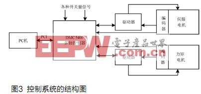
The control system is based on the PC platform, and the DMC5400 multi-axis motion controller is the motion control core. The CPU of the PC and the CPU of the DMC5400 constitute the structure of the upper and lower machines, and the two CPUs respectively perform the corresponding tasks.
As the host computer of DMC5400, PC provides Windows platform and man-machine interface, completes system initialization, track parameter setting, real-time display of motion information, etc., and only needs to send motion commands to the control card in a very small part of time. The lower DMC5400 multi-axis motion controller mainly completes the motion control of the translation motor and the rotary motor, including real-time tasks such as servo drive, program interpretation and high-speed data acquisition. The DMC5400 plugs directly into the PCI slot of a PC and is driven by a dynamic link library.
Motion Control System Software Design
The control system is essentially an open CNC system with DMC5400 as the core. The upper PC and the lower DMC5400 multi-axis controller each have their own CPU, memory and peripherals, which form a separate computer system. Therefore, the characteristics of this structure are fully considered when selecting the development platform of the control software. Because the DMC5400 multi-axis controller adopts the real-time operating system, the complex interpolation operation of the NC program code interpretation work and continuous motion is completed by its internal DSP, which can ensure the timely processing of the operation process and various emergency situations. Relatively speaking, the upper PC only provides the reading of the user interaction part and some state variables, and the workload of the CPU is not very large.
PC software
The composition of the host computer software is shown in Figure 4.
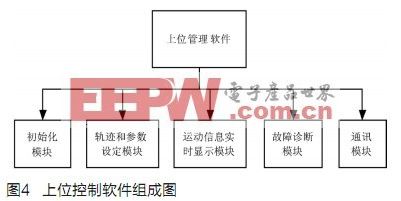
Initialization module: implements functions such as zero calibration.
Trajectory and parameter setting module: According to different motion functions and trajectories, corresponding parameter setting interfaces are provided, including auxiliary functions such as parameter rationality determination and default value provision.
Motion information real-time display module: dynamically collects motion information such as load position and speed through real-time communication with DMC5400. Then, with the display interface with two-dimensional coordinate system developed by CB, the real-time dynamic display of the load motion trajectory is realized, and the left and right soft and hard limit states are dynamically displayed. In addition, the position and velocity data of the load are dynamically displayed in real time in the lower right corner of the interface.
Fault diagnosis module: embedded in each function module, such as the determination of the rationality of the set value, the protection of the keyboard operation function, the interlock of the interface function button, the motor speed limit protection, the position overspeed protection, and the like.
Communication module: Using the dynamic link library provided by DMC5400 to realize communication between the upper PC and the lower DMC5400. It is embedded in each functional module, encompasses all the ways to communicate with the DMC5400, and classifies and encapsulates its main functions. The programmed communication program realizes the communication function of the motion track program and the setting parameters, the command transmission of the upper PC to the DMC5400, and the status feedback of the DMC5400 to the PC.
Lower computer software
The control lower position machine is the direct control stage of the motion control system, and constitutes two independent servo control loops of controllable expansion and controllable attenuation. Its functions include: real-time control of the target motion; control of the operating position and speed of the system by using corresponding control algorithms; and transmitting the detected system status signals to the host computer through the PCI bus. The motion control function of the DMC5400 is very rich and can meet the requirements of most multi-axis motion control systems [3].
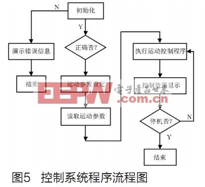
The DMC5400 Motion Control Card provides 32-bit DLL driver programming based on Windows 95/98/Me/NT/2000/XP. The specific programming language can be any of VB, VC, C++Builder. The functions used in the motion function library are mainly as follows: control card and axis setting function, independent motion and interpolation motion function, braking function, position and state setting and query function, I/O port operation function , error code function. Its function returns a value of 0 (the function is executed correctly) or -1 (function execution error). The flow chart of its control system is shown in Figure 5.
 Simulation result analysis
Figure 6~11 shows the three-dimensional coordinate curve of the laser guided bomb space in the semi-physical simulation test and the mathematical simulation test. It can be seen that the test curves agree well under the two simulation modes. Since the difference performance is not obvious in the entire ballistic curve, the corresponding local display curve of the ballistic end corresponding to each coordinate is given.
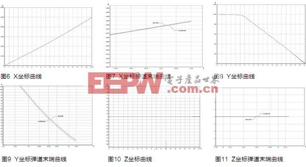
The experimental results show that the simulation of mathematical simulation is stable and the result is good. At the same time, under the same projectile condition, the correlation between semi-physical simulation and mathematical simulation test process is better, and the simulation precision is very high, which reflects the target simulation system. The error into the whole system is very small (target system error accounts for 90% of the total system error), and the designed control system realizes real-time control of spot size and energy.
USB Cable
USB cable assemblies are some of the most popular cable types available, used mostly to connect computers to peripheral devices such as cameras, camcorders, printers, scanners, and more.There are many USB connector types of cable:USB A to USB C,USB C to type-C,USB A 3.1,ect..

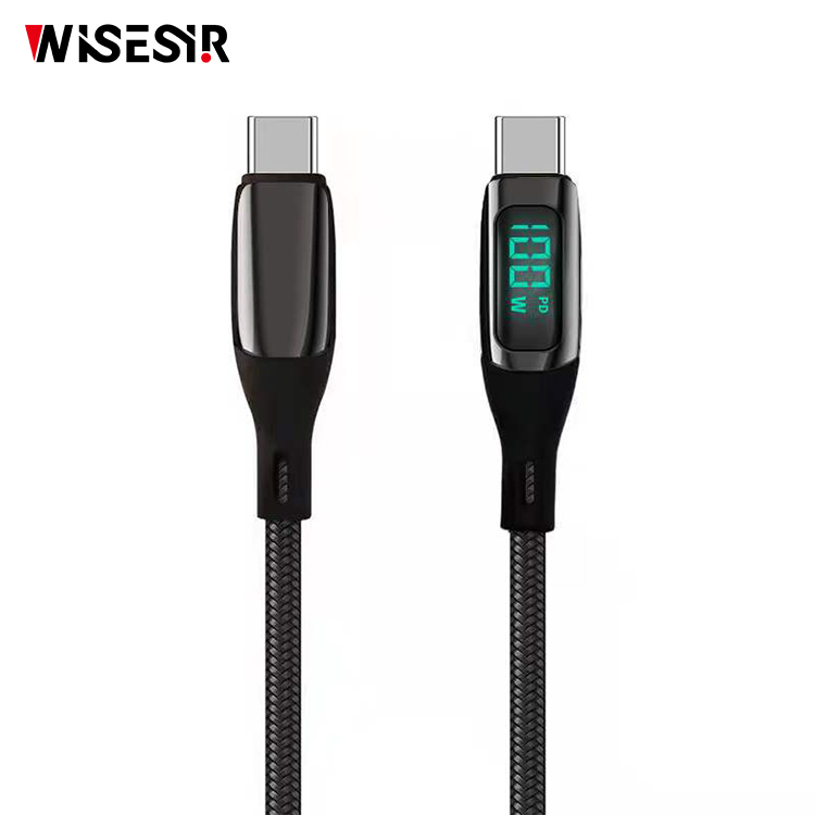
Mobile Data Cable Types,3 in 1 Data Cable,Mobile Data Cable,Magnetic Data Cable Type C
Pogo Technology International Ltd , https://www.wisesir.net
