0 Preface
This article refers to the address: http://
Multimedia Broadcast Service (MBMS) is a mobile TV technology solution based on UMTS (via mobile communication system) proposed by the 3GPP organization. The purpose is to provide a more efficient way for WCDMA and TD-SCDMA networks to multicast or broadcast multimedia information. Transfer to each UMTS terminal. Since 2004, many operators have launched this kind of business. With the passage of time and the approach of the 2008 Beijing Olympic Games, domestic TD-SCDMA mobile phone R&D companies (such as China Post) have been developing based on existing TDs since 2006. - The overall technical solution for the Multimedia Broadcast Service (TD-MBMS) of the SCDMA system.
Handheld TV technology is mainly divided into three categories: from terrestrial digital broadcasting technology, satellite transmission technology and mobile network technology. The first type of technology is represented by DVB-H in Europe, T-DMB in Korea, ISDB-T in Japan, MediaFlo in the United States, and CMMB in China. It is based on terrestrial broadcasting networks and is loosely coupled or relatively independent of mobile networks. Networking; the second type of technology is represented by S-DMB adopted by South Korea, Japan, and some European countries. It is based on satellite transmission, supplemented by terrestrial broadcasting network, combined with mobile network or relatively independent networking; The technology is represented by 3GPP's MBMS and 3GPP2's BCMCS, which is based on mobile networks and cannot be independently networked with respect to mobile networks.
The high bandwidth and sudden multi-user demand of mobile TV services and the serious shortage of bandwidth and capacity resources of mobile networks themselves are difficult to resolve. Therefore, it is not feasible to provide large-scale commercial services for mobile TV in a point-to-point manner, and the mobile TV technology using broadcasting will be an inevitable trend of the business development. 1 Introduction of MBMS technology based on TD-SCDMA
1.1 MBMS overall architecture
MBMS (multimedia broadcast multicast serv-ice) is a multimedia broadcast multicast function defined by 3GPP R6. MBMS provides two modes: broadcast mode and multicast mode. MBMS not only enables plain text low-rate message-like multicast and broadcast, but also enables multicast and broadcast of high-speed multimedia services.
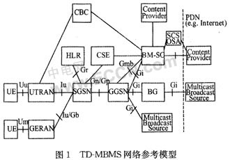
Multicast and broadcast services MBMS is based on the WCDMA/GSM packet network. By adding some new functional entities, such as the broadcast multicast service center BM-SC, the existing packet domain functional entities such as SG-SN, GGSN, RNC and UE, etc. The MBMS function is added, and a new logical shared channel is defined to implement air interface resource sharing. As shown in Figure 1, the main changes to the original network are: adding BM-SC network elements, and upgrading existing network elements in the packet domain to support MBMS-specific interface functions (such as Gmb) and unique channels (such as MICH, MTCH/MCCH/MSCH), unique physical layer procedures (FACH channel selective combining, PTM and PTP switching) and unique business processes (such as subscription). The only new interface here is the Gmb interface.

1.2 MBMS technical advantages
The MBMS defined by the 3GPP in the R6 version refers to a point-to-multipoint (ptm) service in which a data source transmits data to multiple users in a wireless network, and realizes network resource sharing without changing the network structure. In addition to mobile core and access network resources, MBMS can also share more intense air interface resources to improve the utilization of wireless resources. The advantage of MBMS is that it can not only achieve low-speed, low-rate consumer multicast and broadcast, but also realize multicast and broadcast of high-rate multimedia data services, thus making up for IP multicast technology to prevent multiple mobile users from sharing mobile network. Insufficient resources.
In terms of terminals, MBMS still inherits the existing 3GPP standards to the maximum extent, and while the technologies such as power consumption, storage, multimedia processing, and display of the terminal are improved, only the original baseband processing functions are enhanced. Therefore, the MBMS terminal carrying the broadband multimedia service maintains a good uniformity with the existing terminal.
In terms of bandwidth, MBMS can use up to 256 Kbit/s for download and streaming. In terms of interaction, MBMS itself does not define a special uplink channel, but can use the existing uplink control channel to perform service control procedures such as service subscription and service join, and use the uplink traffic channel to implement some interactive services that cooperate with downlink broadcast/multicast. .
In the most aspect, MBMS provides point-to-multicast multimedia transmission mechanism, and resource consumption has nothing to do with the growth of the number of users. Therefore, it has found a fundamental way to save 3G network's very tight air interface resources and Iub port transmission resources and avoid mobile network capacity disadvantages. Solutions. The more users there are, the more obvious the advantages of MBMS in terms of capacity and cost. When the number of multicast users is small or there is no multicast service user, the network can flexibly allocate dedicated channels to users or close multicast traffic channels. The efficient resource management technology unique to mobile networks makes MBMS even more powerful in terms of capacity.
2 The most important development of MBMS technology based on TD-SCDMA at the physical layer
2.1 Single Frequency Network (SFN) Technology
A significant improvement in the physical layer of MBMS is the introduction of a single frequency network (SFN). With the increasing frequency of frequency resources, single-frequency networks have begun to receive more and more attention in both digital TV terrestrial broadcasting and mobile communication technologies. The so-called single frequency network, that is, several transmitters in the same geographical area simultaneously transmit the same signal on the same frequency band to achieve reliable coverage of the area. A single frequency network implemented in MBMS is to transmit the same signal on the same frequency simultaneously at several base stations. The biggest benefit brought by SFN is the improvement of spectrum efficiency. At the same time, the UE (User Equipment) does not need any handover when moving within the SFN, which greatly reduces the signaling overhead.
In the case that the time slot of the transmission broadcast service is configured by the single frequency network, multiple adjacent cells adopt a unified scrambling code (including the Mid-amble code), so that the signals transmitted by the respective cells are completely the same, and the UE only needs to The signals transmitted by multiple cells are multipath processed, and UNT macro diversity can be implemented very simply. But to a certain extent, single frequency networks require receivers to tolerate longer delay spreads. In a single frequency network, adjacent base stations transmit the same signal at the same frequency. These signals are formed by the same process of channel coding, channel mapping, spreading, puncturing, interleaving, modulation, and the like.
The most important technique in single-frequency network applications is to require that the signals broadcast by each transmitter be synchronized in frequency and time. Frequency synchronization requires that each single-frequency network transmitter operate at the same frequency; for multi-carrier modulation, the frequency of each sub-carrier is also required to be equal. Frequency synchronization can be achieved by phase-locked synchronization with the same reference frequency (typically using a 10 MHz reference frequency from GPS satellites).
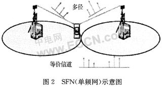
As shown in FIG. 2, at this time, for the mobile phone receiver, signals from different base stations can be equivalent to multipath signals. Since the receiver does not need to distinguish whether the signals are from different base stations, the complexity is greatly reduced. In the original base station, there is co-channel interference, and the mobile phone needs to perform complicated calculation to eliminate interference. However, in the SFN, since the multipath signal is rich, the receiving performance is greatly improved, thereby improving the spectrum utilization.

2.2 Improvement of single-frequency network (SFN) technology in physical layer implementation
2.2.1 Dynamic single frequency network networking method
Initially used in the standard is the SFN operation method based on the O&M configuration. This method is less flexible and cannot properly allocate users accessing the MBMS service. This is a static MBSFN method. The static MBSFN method is simple to apply, although the complexity of MBSFN can be significantly reduced, but the shortcomings of the static SFN method are obvious:
(1) The SFN area of ​​the O&M mode needs to set the entire area to be very large in order to cover the user positions that are difficult to cover. Therefore, such a scheme will inevitably cause waste of radio resources and transmission resources, because some cell resources that are not accessed by the UE without the MBMS service are idle.
(2) The larger the area covered by the static SFN area, the more wireless resources and transmission resources are wasted. However, the user rationing scheme in the MBSFN area has not been improved in time. This contradiction can be solved by the dynamic SFN scheme.
The dynamic SFN method is to first configure an initial cell. When the mobile terminal applying for the MBMS access service is in the edge zone, when the terminal is in the SFN protection zone, the terminal sends an SFN UP-DATE INDICATION message to request the MCE to increase the neighboring cell to the final cell. Go inside the SFN area.
The dynamic SFN method is an improvement over the original static SFN method, because the original static SFN is to fix all cells within the same MBMS service area as SFN areas, although the method is simple but for tight wireless network resources. A big drawback. The dynamic SFN firstly sets the cell that provides the MBMS service at the current moment and the cell adjacent to them as the initial cell, and then sends a request to the superior according to the requirement of the mobile terminal of the user terminal, dynamically changing the range of the SFN area, although the process is more complicated. However, the wireless networks of those cells that are idle are idle and can be used for other services, which is a highly desirable method. In the dynamic SFN method, there is a method based on a simple selection scheme, in which all cells adjacent to a cell with MBMS UE access are classified into a final area, and now, for the purpose of improving network resource utilization, according to the network topology Structure and MCE capabilities and reliability, and an improved method of dynamic SFN, that is, only the cells adjacent to two cells with MBMS UE access are allocated to the final area, and those only one with MBMSUE The neighboring cells are excluded from the adjacent cells.
2.2.2 Development and improvement of single frequency network (SFN) technology
The advantages of single-frequency networks are obvious, but they also have certain limitations. TD-SCDMA is a time division duplex (TDD) system. The uplink and downlink links occupy the same frequency, while the typical MBMS service is downlink broadcast, apparently in TD- It is not suitable to use a single frequency network with a single frequency network in SCDMA, which will face the problem of spectrum resources and base station cost; it may cause the time slot (downlink) of MBMS frequency and the same time slot (upstream) of non-MBMS frequency point. Strong interference. In addition, the individual frequency points are also not conducive to resource planning and sharing receivers with the N-frequency system. Therefore, the SFN-based union time-slot net-work (UTN) technology is introduced in TD-MBMS, and the UTN network improves the multipath delay requirements for mobile phone receivers.
TD-SCDMA is an increasingly important part of the 3G standard. At present, the TD system adopts an N-frequency point networking mode, and one cell has one primary frequency point and (N-1) secondary frequency point resources. Usually N=3, that is, 5 MHz co-frequency networking, as shown in Figure 3.

In the N-frequency system, only the primary frequency point in each frame transmits TS0 (time slot 0) in a broadcast manner, and the secondary frequency point does not transmit the time slot. The main frequency point usually needs to be frequency-planned between adjacent cells, and try to avoid the same main frequency point in the adjacent interval.

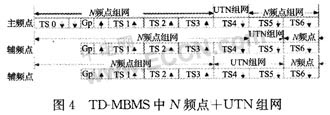
Figure 4 shows a schematic diagram of the joint network of N-frequency and UTN. The downlink time slot can be configured as a UTN or N frequency point time slot; the UTN occupied time slots of different frequency points in the cell can be the same or different; but the UTN time slot allocation of the same frequency point of the adjacent cells is the same. The UTN time slot is used to transmit an MBMS broadcast service, in which a plurality of base stations participating in the broadcast transmit the same signal, and therefore, the UTN is actually an SFN network.
The UTN time slot uses a common Midamble code, a scrambling code, that is, the parameters of the local cell and the neighboring cell are the same; between the neighboring cells, the data transmitted by the time slot is also formed by the same processing of the same data. For other N-frequency time slots, the cell-specific Midamble code and scrambling code are used. TS6 (time slot 6) is usually not used as a UTN time slot. Otherwise, when the mobile phone receives the MBMS service at the secondary frequency point, there may not be enough time to switch to the TS0 of the primary frequency point due to the limitation of the radio frequency device.
In fact, the UTN time slot can be viewed as a separate SFN wireless network that is time division multiplexed with the N-frequency network. UTN can be used for regional networking. The same UTN time slot can form different UTN networks in different regions, but different UTN networks should be geographically isolated. A typical scenario is that different cities use different UTN networks to play their respective TV channels. The UTN frequency and time slot resources of the N-frequency system can be flexibly configured, for example, more downlink time slots are allocated to the UTN; the number of UTN time slots at each frequency point is different to adapt to services of different rates.
3 conclusions
In the future of mobile communications, MBMS is still one of the main application services to increase operating revenue. The main considerations of LTE include reducing latency, increasing user data rates, increasing system capacity and coverage, and reducing operating costs. The flexibility and efficiency of the combination of SFN and UTN networking is evident. MBMS technology can greatly improve the utilization of network resources, especially valuable air interface resources, and can realize a variety of rich video, audio and multimedia application services, providing a broader space for the development of 3G.
Connector 3.96Mm Pitch,Ressure Welding Bar Connector,Wire To Board Power Connector,Tcj6 Wire-To-Board Connector
YUEQING WEIMAI ELECTRONICS CO.,LTD , https://www.weimaiconn.com
