Abstract: This article applies MSTR's MST717C display driver chip to drive TFT liquid crystal display. As a vehicle-mounted multimedia information display terminal, it has the characteristics of low cost, good display effect and simple application. Focus on the design of the MST717C peripheral circuit and the development of the MSTAR company Maria software architecture, which will help the TFT LCD driver developers.
Key words: TFT LCD screen; MST717C; vehicle display terminal
This article refers to the address: http://
0 Introduction At present, various multimedia technologies are constantly developing, and consumer electronic products based on multimedia technology are exploding. The 32-bit processor led by ARM, MIPS, etc. shows great advantages in portable multimedia terminal applications and occupies the vast majority of market share. However, multimedia embedded applications built with 32-bit processors often require external SDRAM and FLASH to work with them, which makes the whole system in a relatively high-cost state, while the traditional 51 single-chip microcomputer operates at a lower frequency. Problems such as its own architecture do not have multimedia image processing capabilities. This article uses MSTR's MST717C series chip developed for small and medium-sized LCD screens. It has video decoding capability, supports multiple analog video signal inputs, built-in zoom engine, built-in 51-MCU, 16-color OSD display, etc. Function, very suitable for car multimedia display terminal applications.
1 System overall design MST717C supports NTSC, PAL, SECAM video system signal input, built-in 2D comb filter, 2 CVBS input, 2 S-Video input, support analog RGB input (such as analog VGA signal from PC) . Supported video formats such as 480i, 480p, 576i, 576p, 720p, 1080i, analog RGB signal resolution supports 640 × 480, 800 × 480, 800 × 60-0. Built-in brightness (Brightness), Contrast, Saturation and Hue adjustment, built-in 3-channel GAMMA curve adjustment, built-in zoom engine, up to 1366 × 768 resolution. Digital PWM controller, programmable control 40~70kHz frequency range data enable, line sync signal output, 150~300Hz frequency range field sync signal output. Built-in 51-MCU, 3-wire serial bus interface, built-in hardware I2C, SPI, support 16 colors 256 programmable characters OSD.
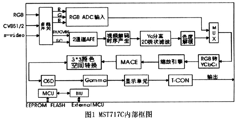
2 system hardware design
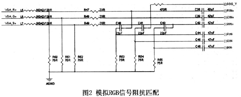
2.1 MST717C peripheral circuit analog video signal input needs impedance matching to the ground, as shown in Figure 2 is the analog RGB input impedance matching circuit. The input signal first isolates the high frequency noise through a 120R magnetic bead, and then performs 75 Ω impedance to ground. The match is matched to the 35 Ω input impedance and a 47nF ceramic capacitively coupled input is placed close to the chip. For CVBS, ground impedance matching and input impedance matching are also required. The typical value is 62Ω or 75Ω, and the coupling capacitor can be 0.1μF ceramic capacitor.
2.2 LED backlight drive circuit Common TFT LCD panel module backlight is mainly divided into CCFL and LED. CCFL (Cold Cathode Fluorescent Lamp) technology is mature, low cost, high brightness, usually above 400cd-/m2; It is a high-voltage AC drive (several hundred to thousands of volts), the drive circuit is complex, the efficiency is low, and the heat is large. The main feature of LED backlight is low voltage DC drive (10 volts to tens of volts). The drive circuit is simple, high efficiency and low heat generation. The disadvantages are high cost, low brightness and poor color reproduction. At present, some large manufacturers of LCD modules have solved the problem of low backlight brightness by increasing the number of LEDs, and some can even reach 600 cd/m2. In addition, by adopting RGB ternary color LED to compensate color reproduction ability, the effect is better than CCFL mode. All major manufacturers are optimistic about LED backlight mode, which is also the main trend of LCD panel backlight development.
Here we use the 8 inch widescreen LCD module A1080TN03 developed by Innolux, with a physical resolution of 800×480, 260,000 colors, LED backlight, typical driving voltage is 10V, driving current is 100~200mA. The backlight power input is 5V, and the DC-DC boost chip KB4317 is used to stabilize the output at 10V.
2.3 Audio Signal Processing and Amplifying Circuit PT2314 is a low-cost and high-performance four-input digital sound processing chip developed by Taiwan Pucheng Technology. It supports volume, left and right channel balance, and high and low sound (Treble & Bass). Controls such as Loudness support Selectable input gain and support standard I2C interface. The PT2314 control port I2C is connected to the software analog I2C interface of the MST717C. It should be noted that the I2C transmission line needs to be pulled up to ensure the reliability of the transmission.
3 system software design
3.1 Maria software overall framework Maria is the public version of the driver software source code introduced by MSTAR for the MST71X series chip application. The source code is mainly based on KEIL C51 language, but due to its relatively complicated, the source code is large (tens of thousands of lines) ), bringing some difficulties to ordinary users. The style of the Maria source code is somewhat similar to the style of the Linux kernel source code, mainly including Device, inc, kernel, msFunc, msLib, osd, project, tv and other folders.
The Device folder is the driver code of the user-specific device. Here we add the driver code of PT2314 and put it in a name of PT2314. In the file of C, it is mainly to initialize the PT2314 chip and give some interface functions of the sound operation class.
The Inc folder is mainly a number of header files, including the global variable application Global. h, the word header file Font. h, based on the 51 core microcontroller header file mcu. h, as well as header files such as various screen parameter definitions.
The Kernel file mainly contains the main function main. c, mcu initialize mcu. c, global variable initialization to achieve Global. c, interrupt service function implementation isr.c, debugging help function to achieve Debug. c, MST7lX series chip register configuration function mStar. c and some commonly used functions misc. c and so on.
The msFunc file is mainly the implementation of some function operation class functions, such as the key class Keypad. c, infrared remote control class IR. c, IrFunc. c, OSD menu class msOSD. c, game class Game. c, menu function class MenuFunc. c and so on.
Under the msLib file are some dynamic library files about the DSP processor, which are hidden from the developer and can be ignored by the user.
The Osd file contains some font and image files. The user can add the desired text (such as Chinese characters) and binary icons to the corresponding file after taking the modulo software.
The project file is mainly about KEIL C project files, divided into 64k and 128k, generally 128k is better.
Tv is some of the operational functions that MSTAR writes specifically for analog TV users.
3.2 The specific implementation of each function
3.2.1 Audio Processing Chip Driver This system mainly expands the sound processing chip PT2314 on the periphery of the MST717C. The PT2314 supports the standard I2C protocol. It shares the MTP7 and GPI01 software analog I2C of the MST717C with the 24LC16. The hardware I2C of the MST717C is used as the chip program programming function. 
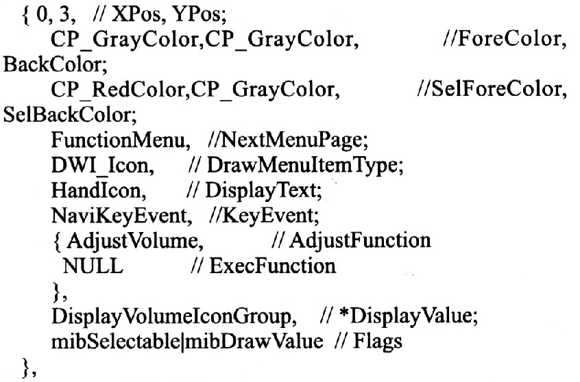
3.2.2 OSD Menu Customization Maria provides a standard OSD menu framework that includes color, contrast, brightness, screen display area adjustment, and timing shutdown. The Maria OSD menu contains a three-level menu, the first menu root directory root; the second level menu contains images, volume, function, system, time, a total of five directories; three-level directory, each secondary directory internal menu items, such as under the image menu Contains four levels of menus: brightness, chroma, contrast, and language. Users can add and delete any level menu by themselves. In this system, the PT2314 audio processing chip is selected to support four-channel stereo input. The host can control the volume, bass, treble, balance and other options through the I2C bus, so the volume is in the secondary directory. Create three levels of three levels: Volume, Bass, Treble, and Balance. MenuTbl. The corresponding menu array MenuItemTypecode AudioMenuItems[]={) is created in the h file: MenuItem-Type is a data structure, and its prototype is 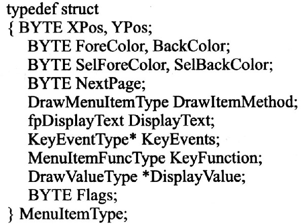
Contains the relative position of the menu item, the background color, the color when selected, the associated next level menu, menu drawing type, display text, button corresponding event, function, display type, logo, and so on. The meanings can basically be understood by the text description. It should be noted that the MST717C OSD menu only supports 16-color display. Here is a sub-menu of PT2314 as an example.
3.2.3 Button events
The user button uses the ADC key value sampling difference. When different buttons are pressed, the ADC gets different voltage values ​​(see Figure 4). The program main loop checks whether the key is pressed by continuously executing the key scan function Key ScanKeypad(). If a key is pressed, the program first compares it with the last key value (g ucLastKeypad). If it is equal, it executes the repeated key event EventRepeatProcess(); otherwise, it executes the key event EventProcess(), and the key is executed. The value is set to g ucLastKeypad.
The Maria key event is primarily done by a data structure defined as a KeyEventType type. The first element in the data structure is the key input state, which contains two input states INPUT PRESS and INPUT_HOLD, where INPUT_PRESS is the button press state, which only represents the state when pressed; INPUT_HOLD is the continuous state when the button is pressed, which is equivalent For quick combos. The second element is the event that will be executed when the button is pressed, and its data structure is MenuItemActionType. Note that the Menultem-ActionType events corresponding to the same button are different for different KeyEventType events, so as to distinguish the different functions performed by the same button in each directory. The last element is the input type InputPortType, which is an enumerated variable, which represents different video source state key inputs. For example, when the Power button is input, it corresponds to Input_AllPort, that is, the button is valid in any state; and the remote control button 1 is input 1 < 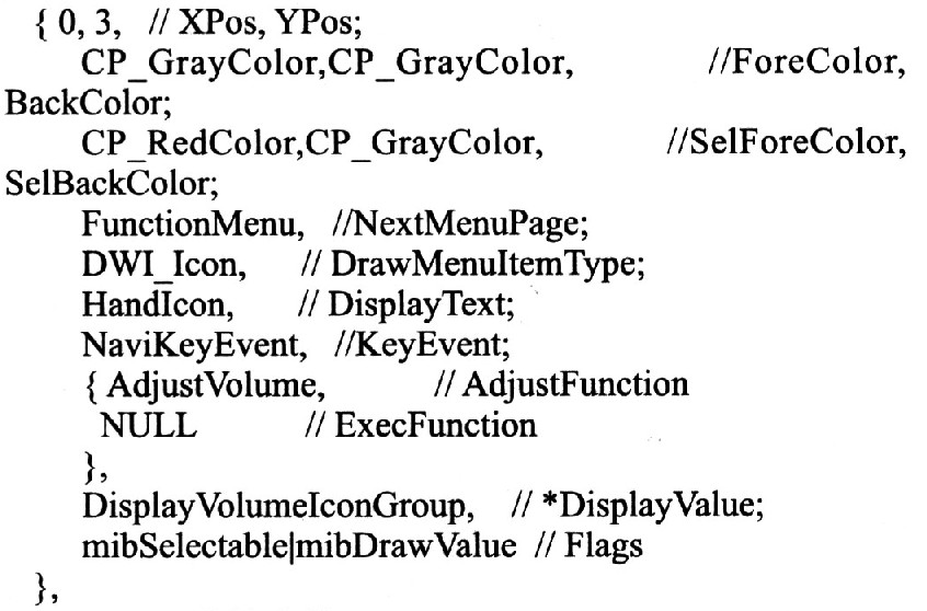
4 Conclusion MST717C is a very cost-effective display driver chip, and requires very few peripheral devices, which is very suitable for automotive display applications. It should be noted that the display driver has higher requirements on the stability of the power supply. The PCB layout is preferably divided between the analog ground and the digital ground to ensure the stability of the video signal. For example, the cost allows the four-layer board to be selected. The power supply is not easy to handle, and the VCOM voltage must be stable to ensure the stability of the displayed image. In addition, the Maria software architecture is somewhat complicated, and the developer's C language requirements are somewhat high. It takes a certain amount of time to read the code and then carry out its own secondary development.
Remote Controller Socket Converters
Remote Power Socket,Remote Control Socket Adaptors,Remote Control Plug Adapters,Remote Control Socket,Remote Power Switch
NINGBO COWELL ELECTRONICS & TECHNOLOGY CO., LTD , https://www.cowellsockets.com
