Embedded control systems are widely used in industrial control because of their low power consumption, low cost, high performance, etc., and stepper motor drive control technology is one of the key technologies in embedded control systems. In the design of stepper motor control system, the traditional method is to realize stepper motor control with logic circuit or single chip microcomputer. Although this method is feasible, it has certain limitations due to complicated circuit and difficult adjustment after manufacture. With the development of embedded technology, more and more intelligent small devices with interface control functions penetrate into people's lives. Based on the Qt technology in the embedded field, the developer designed a set of intelligent control system with human-computer interaction interface applied in the field of industrial control. Qt is the famous iconic product of Norwegian TrolLTEch. Using C++ as the programming language has become The mainstream of free software development on Linux with the C++ GUI toolkit is the foundation of the popular KDE desktop environment on Linux. Qt/Embedded is a Qt version of the embedded system developed by the famous Qt library developer Trolltech. Qt is the Server/Client structure, which continues the powerful function of Qt on X. Xlib is abandoned at the bottom, and only frame buffer is used as the underlying graphics interface. The Qt/Embedded class library is fully packaged in C++ and provides all the functionality required by application developers to create state-of-the-art graphical user interfaces. Qt/Embedded is fully object-oriented, easy to extend, provides a rich set of widgets, and allows for true component programming.
1 hardware circuit design
1.1 System overall block diagram
The hardware part of the control system mainly consists of: stepper motor, TA8435H, S3C2440 microprocessor, optocoupler, touch screen. The hardware structure of the control system is shown in Figure 1.

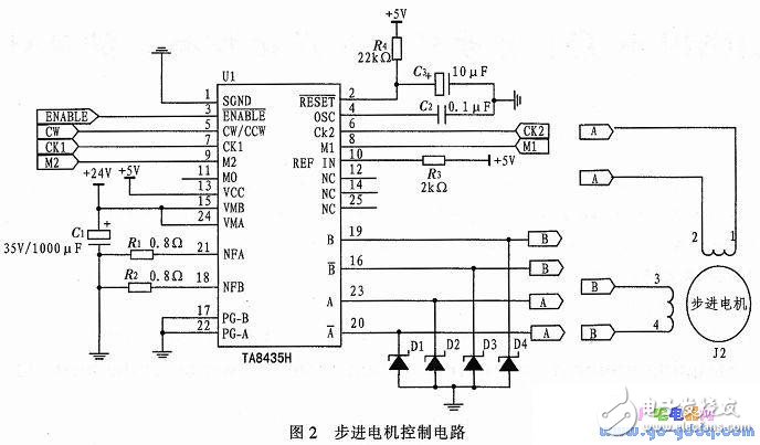
The system uses Qt to design and develop the man-machine interface of the embedded control system under Linux. The stepper motor is controlled by the touch screen interface to control the rotation direction and rotation speed of the stepping motor and the subdivision mode. 1.2 Circuit Design 1.2.1 SC2440 and TA8435H Circuit Design The hardware core circuit of this system is a stepper motor control circuit composed of S3C2440 processor, TA8435H stepper motor driver chip and stepper motor. The stepper motor control circuit is shown in Figure 2.

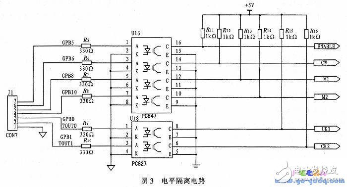
In the stepping electric control system, the S3C2440 chip with arm920t as the core is adopted. This chip is a high-performance microprocessor produced by Samsung, which has the advantages of low power consumption, high performance and low price, and is in many fields. Both got the app. This paper selects the chip as the core processor and implants it into the Linux system to complete the interactive control of the stepper motor through the touch screen. The S3C2440 chip has 289 pins, of which 30 are multi-function general-purpose I/Os, respectively GPA ~ GPJ, GPA has 25 output ports, and the rest can be configured as input or output as needed. In order to achieve reliable control of four motors, the system selects the GPB port as the control port. The port has 8 pins, which are GPB0~GPB8, so the real-time control of the stepping motor can be completed. TA8435H is a single-chip sinusoidal sub-stepping motor drive special chip produced by Toshiba. TA8435H can drive two-stepping motor, and the circuit is simple and reliable. TA8435H stepper motor driver chip pin 4 external capacitor capacitance determines the chip's internal drive stage chopping frequency, the capacitance used here is 0.01μF. Since the motor requires a drive current of 0.1 A, set the REF IN pin high and Rnf = 0.8 Ω. The stepper motor interface requires the use of a fast recovery diode (D1 - D4) to bleed the winding current. 1.2.2 Circuit Reliability Design In order to improve hardware reliability and effectively suppress interference, a level isolation circuit consisting of optocoupler TLP521-4 and TLP521-2 chips is added between S3C2440 and TA8435H to control the S3C2440 processor control signals. Into the motor controller for level shifting and isolation. The level isolation circuit is shown in Figure 3. The S3C2440 processor GPIO port and PWM output pin are level-isolated by the optocoupler TLP251.

2 software design
Since the motor has precision, speed, stability, direction and other requirements in the actual industrial control, the design should realize the selection of the forward, reverse, rotational speed and subdivision modes of the motor through the interaction of the touch screen buttons. The TA8435H chip has two modes of forward and reverse rotation, and the motor is controlled by the pin CW/CK1/CK. The subdivision mode can also be selected by the high and low levels of the M1, M2 input pins. When M1M2 is 00, the stepper motor works in the whole mode, there is no subdivision; 10 is half step mode, 01 is 1/4 mode; 11 is 1/8 subdivision mode. In low speed operation, 1/4 or 1/8 subdivision mode can be selected to improve the step angle accuracy; in high speed operation, the whole step or half step mode can be used to improve the stability of the stepper motor operation. Noise and vibration of small stepper motors. The speed of the stepping motor is determined by the frequency of the pulse signal. The generation and control of the pulse signal is actually generated by the CPU. The duty ratio of the pulse signal is generally about 0.3-0.4. The higher the motor speed, the higher the duty cycle. Big. In this design, the motor speed is controlled by changing the timer parameters, and the PWM output that has generated other frequencies and duty cycles controls the stepper motor. The PWM output signal duty cycle formula is
Female Header,Female Header Pitch 2.54Mm,Smt Female Header,In-Line Patch Female Connector
Shenzhen Jinyicheng Electronci Technology Co.,Ltd. , https://www.jycconnector.com
