
The magnet of the 40 T steady-state strong magnetic field device of the strong magnetic field center of the Chinese Academy of Sciences consists of two parts: the inner water-cooled magnet and the outer superconducting magnet. They all have certain requirements on the voltage stability of the magnet power supply. At present, the rectification part of the inner water-cooled magnet power supply is a three-phase thyristor rectifier circuit, and the output voltage ripple is large. This paper proposes a new rectification scheme.
Since the introduction of the midpoint hoop inverter [1] by Professor Akira Nabae of Japan in 1981, more and more three-level circuits have appeared. Among them, the Buck three-level (TL) DC converter has low voltage withstand voltage and low output ripple, which is suitable for high voltage and high current applications. This paper describes the basic situation and advantages of the Buck TL converter, and proposes a water-cooled magnet power rectification scheme using a Buck TL converter combined with a three-phase uncontrolled rectifier circuit instead of a thyristor rectifier circuit. In this paper, the parameters calculation and simulation design of the circuit are carried out, and the simulation results are analyzed.
1 Introduction
1.1 Basic situation
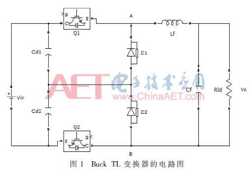
The circuit diagram of the Buck TL converter is shown in Figure 1. Cd1 and Cd2 are voltage-divided capacitors with large and equal capacitance. Under ideal working conditions, their voltage is half of the input voltage Vin; Q1 and Q2 are switching tubes, D1 and D2 are freewheeling diodes; Lf is the filter inductor, and Cf is the filter. Capacitor, Rld is the load.
Buck TL converters are similar to typical Buck converters: they are DC/DC buck converters; both can be controlled by PWM; when the inductor current is continuous, Vo=DVin (D is the duty cycle); There is an LC filter circuit between the output and the load. The difference is that the Buck TL converter has two switching tubes Q1 and Q2, which are interleaved and the driving signals are 180° phase angle difference; the voltage input to the LC filter has three values ​​of Vin, 0.5Vin and 0; When D>0.5 and D<0.5, the converter has two modes of operation.
1.2 Advantages
1.2.1 Voltage control
When the inductor current is continuous, Vo=DVin. Therefore, the Buck three-level converter has good control characteristics for the output voltage.
1.2.2 Voltage stress
In the same case of Vin, the voltage stress of the Buck TL converter is only half of the input voltage, which is one-half of that of the classic Buck converter, which greatly improves the working condition of the switching tube and facilitates the selection of the switching tube. 2].
1.2.3 Voltage ripple
Under the same external conditions, the Buck TL converter has a smaller ripple of the output voltage than the conventional Buck converter.
2 parameter calculation
Combined with the actual situation of the water-cooled magnet power supply circuit and the rectification scheme proposed in this paper, the parameters of the Buck TL converter are designed. The load takes the pure resistance Rld=5 Ω; the switching tube takes the IGBT and the switching frequency is 10 kHz.
2.1 input voltage
As shown in Figure 2, the three-phase voltage is input to the thyristor rectifier circuit via the transformer, and the line voltage RMS is V1 = 610 V. According to the principle of the three-phase uncontrolled circuit, the output DC voltage average value V2=1.35V1=823.5 V.

The output voltage of the three-phase uncontrolled circuit contains 6, 12, 18 and other subharmonics in addition to the DC component, of which the 6th harmonic is the largest. It is known that the m pulse rectification voltage harmonic amplitude [3] is:
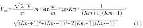
Substituting n=6, m=6 (K=1), and obtaining V6m=47.07 V.
Ignoring high-order ripple, the input voltage of the Buck TL converter is vin=823.5+47sin600Ï€tV.
2.2 voltage divider capacitor
First, analyze the charging process of the voltage divider capacitor. The Buck TL converter has three-level and two-level operation modes [4], and is analyzed in the three-level mode. The main waveform in the three-level mode is shown in FIG.

When D>0.5, the converter works in Three-Level Mode (3L Mode).
(1) Switch mode 1
T0-t1 phase and t2-t3 phase. Q1 and Q2 are turned on, the inductor current iLf rises, and the AB terminal voltage VAB=Vin; at this time, no current flows through Cd1 and Cd2.
(2) Switch mode 2
T1-t2 stage. Q1 is turned on, Q2 is turned off, iLf is decreased, VAB = 0.5 Vin; at this time, Cd1 is discharged, and Cd2 is charged.
(3) Switching mode 3
T3-t4 stage. Q1 is turned off, Q2 is turned on, iLf is decreased, VAB=0.5 Vin; at this time, Cd1 is charged and Cd2 is discharged.
The equivalent circuit of the switch mode 2 and the switch mode 2 is shown in Fig. 4.
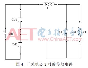
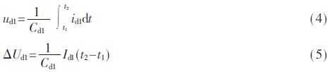
As shown in Fig. 4, Cd1 is discharged and Cd2 is charged. Let the currents through Cd1, Cd2, and Q1 be id1, id2, and iq1, respectively, and the voltages across Cd1 and Cd2 are ud1 and ud2, respectively. Cd1 = Cd2 is known. Knowing Kirchhoff's law that id1+id2=iq1, Vin=ud1+ud2, the amount of change in the two capacitor voltages is equal at any time, ie Δud1=Δud2. The formula for charging and discharging capacitors is:
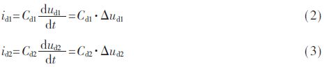
It can be derived that id1=id2=0.5iq1.
Let the capacitance voltage change in the t1-t2 phase Δud1=Umd1. Take Umd1 as 10% of Ud1, then Umd1=0.1·0.5Vin=41.2 V. Let the output voltage stabilize at 500 V, then the load current iR = Uo / Rld = 100 A. Combine iq1=iL, IL=IR, and substitute the capacitor charge and discharge formula:
The score pressure capacitor Cd1 = Cd2 = 9.53 × 10 -5 F.
2.3 Output filter
It is known that the maximum harmonic of the output voltage is 6th harmonic, and the cutoff frequency is 300 Hz, which can be substituted.
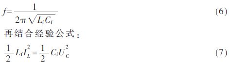
It can be calculated that L = 2.65 × 10⁻³ H, and C = 1.06 × 10⁻⁵ F.
3 partial voltage capacitor equalization problem
The normal operation of the Buck three-level converter is that the voltages of the two voltage divider capacitors remain equal. However, when the actual circuit is running, due to the different control circuit, drive circuit or two switch characteristics, the on-times of the two switch tubes will be different, and the energy they receive or provide will be different, eventually resulting in unequal voltages of the two capacitors.
The basic idea to solve this problem is to detect the voltage of the two capacitors. If Ud1 is greater than Ud2, increase the Q1 conduction time and reduce the Q2 conduction time, and vice versa. Thus, the two capacitor voltages are not fluctuating and can be stabilized around 0.5 Vin. During the simulation, the two capacitor voltages can be sampled for comparison, and the pulse-on-modulation (Pulse Width Modulation, PWM) is used to adjust the on-time of the switch.
In addition to the control loop that equalizes the capacitor voltage, there is a voltage loop that maintains the balance of the output voltage.
4 simulation design
Using Matlab Simulink to build a replacement thyristor rectifier circuit, namely three-phase uncontrolled rectifier circuit plus Buck TL converter. The original rectification scheme and the new rectification scheme are shown in Figure 5 and Figure 6, respectively.
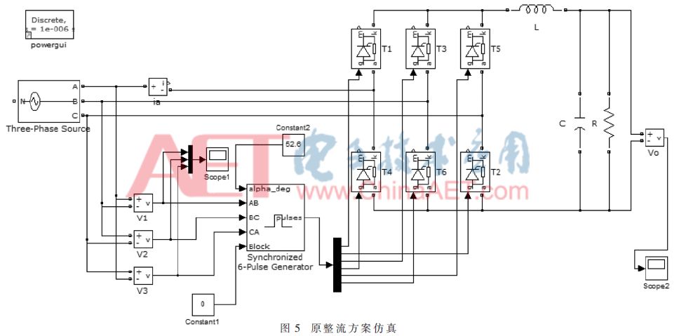
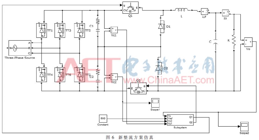
Set the parameters and perform Simulink simulation.
5 Simulation results analysis
Set the output voltage to 500 V and analyze the output voltage with an oscilloscope and FFT tool.
Figure 7 shows the simulated output voltage fluctuation Δu1 of the original thyristor rectification scheme is approximately 400 V.
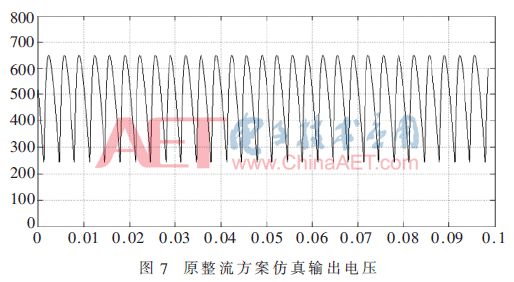
Figure 8 shows the DC and main harmonics of the original rectification scheme simulation voltage. The DC quantity UT0=498.15 V, the 6th harmonic UT6=168.24 V, the 12th harmonic UT12=52.77 V, and the 18th harmonic UT18=24.35 V.
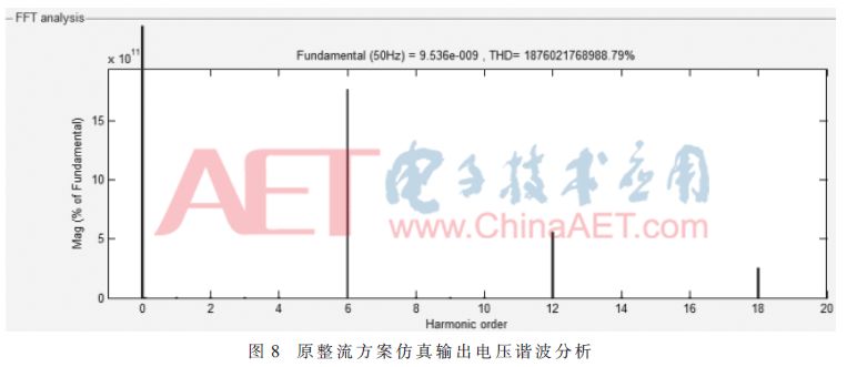
Figure 9 shows the simulated output voltage fluctuation Δu2 of the new rectification scheme not exceeding 5 V.
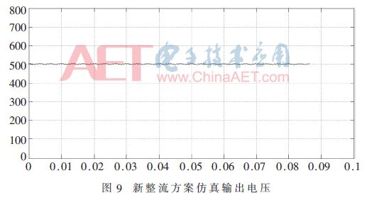
Figure 10 shows the DC and main harmonics of the new rectification scheme simulation voltage. The new rectifier scheme simulates the voltage DC UB0=500.8 V, the 6th harmonic UB6=1.8 V, the 12th harmonic UB12=0.62 V, and the 18th harmonic UB18=0.52 V.
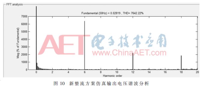
Comparing the data, it can be seen that compared with the original thyristor rectification scheme, the new rectification scheme using the Buck TL converter has a smaller error and a more stable output voltage, and the harmonics are also greatly reduced.
6 Conclusion
In this paper, the method of parameter design is given by analyzing the working principle of Buck TL converter. The solution to the problem of voltage divider capacitance equalization is proposed and implemented in the simulation circuit. Finally, the simulation circuit is run to conclude that the new rectification scheme using the Buck TL converter can greatly reduce the output voltage ripple and increase the voltage stability.
Disposable Vape,Disposable Vape Pen,Disposable Vape Elf Bar Lux,Disposable Vape Pod Device
Shenzhen Zpal Technology Co.,Ltd , https://www.zpal-vape.com