
Single-phase motor wiring diagram and principle There are many electricians who are not clear about the wiring of single-phase motors. Xiaobian first talks about the principle of forward and reverse of single-phase motors.
A single-phase motor has two sets of coils, one common end, one running end, one starting end, and a capacitor connected between the running end and the starting end. When the power is connected to the common terminal and the running terminal, the motor rotates forward; when the power is connected to the common terminal and the starting terminal, the motor is reversed; only the single-phase reversible motor with the same cross-sectional area of ​​the running coil and the starting coil can be reversed, otherwise it is reversed. Can not carry the load.
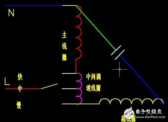
Single-phase motor forward and reverse wiring diagram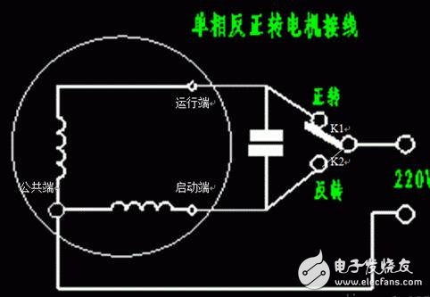
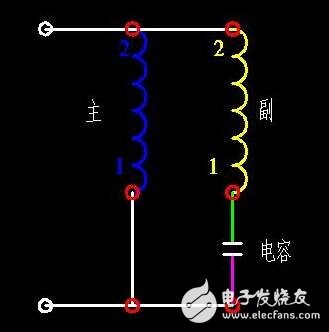
A single-phase capacitor motor has two windings, a start winding and a running winding. The two windings are spatially different by 90 degrees. A large-capacity capacitor is connected in series on the starting winding. When the running winding and the starting winding pass through single-phase alternating current, the current in the starting winding is advanced by 90 degrees from the current of the running winding due to the action of the capacitor, reaching the maximum first. value. Two identical pulsed magnetic fields are formed in time and space, so that a rotating magnetic field is generated in the air gap between the stator and the rotor. Under the action of the rotating magnetic field, an induced current is generated in the rotor of the motor, and the current interacts with the rotating magnetic field. The electromagnetic field torque causes the motor to rotate.
Generally, the running winding (main coil) has a thicker wire diameter, and the starting winding (secondary coil) has a smaller wire diameter. The multi-meter starting winding is slightly larger than the running winding.
Single-phase motor starting principle is divided into: 1, resistance start type (refrigerator motor, etc.); 2, capacitor start type (woodworking planer motor, etc.); 3, capacitor operation type (washing machine, electric fan, etc.); 4, capacitor start operation formula.
Capacitor-activated motor is powered off after the motor is started. The principle of power-off is that there is a centrifugal switch on the motor shaft. When the speed is reached, the switch will be broken. If the start-up line package is broken, it will burn out. Capacitor running motor The capacitor is working when the motor starts or is running normally. If the capacitor capacity becomes smaller, the motor will start hard, the fan will slow down, and the wind speed will reduce the fault.
Single-phase motor forward and reverse wiring method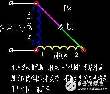
In this case, 1 (2) of the primary coil is connected to 2 (1) of the secondary coil, so that it is transmitted positively, and vice versa.
1(2) of the primary coil is connected to 1(2) of the secondary coil, and this is reversed.
In the above two figures, a general conventional single-phase motor can be used, regardless of the parameters of the primary coil and the secondary coil.
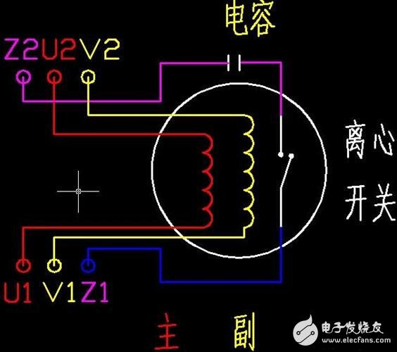
There is also a single-phase motor that needs to be reversed during operation. However, using the above method is more troublesome, and automatic control is required. The device needs more, so it appears that the single-phase motor without the primary and secondary coils is The parameters of the primary and secondary coils are the same. This single-phase motor that does not divide the primary and secondary coils can be used in addition to the above method.
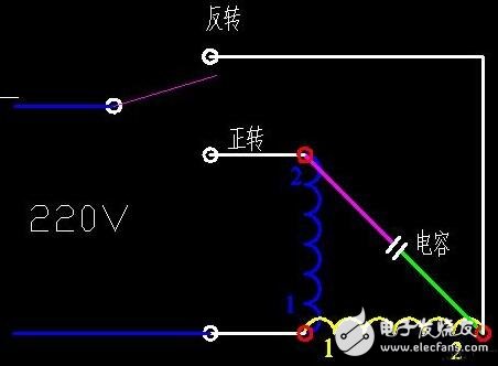
The first picture is the same as the second one, and the second one is clearer.
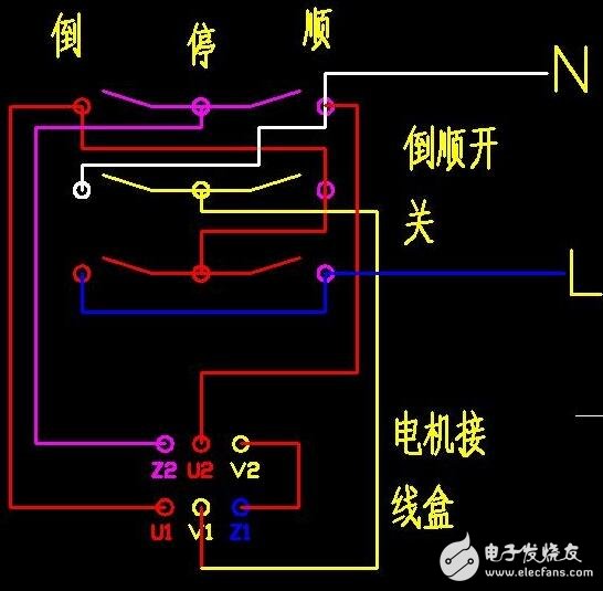
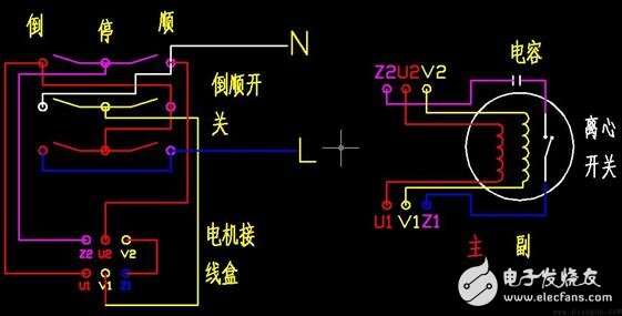
The second figure can also be transformed into this way, so that the inversion can also be achieved.
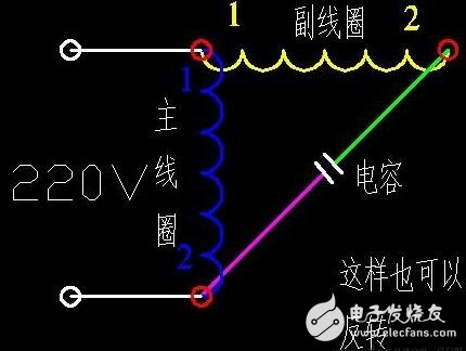
There is also a way to draw a single-phase motor.
The single-phase motor controlled by the reverse switch is reversed.
Floor fan motor wiring diagram.
The single-phase motor is reversed and controlled by a contactor.
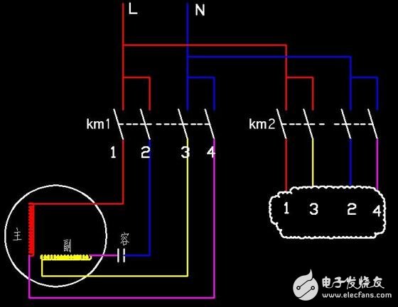
The red and pink wires are swapped underneath KM1, or the blue and yellow wires are interchanged and the motor can be reversed.
The secondary line of KM1 and KM2 uses the normal forward and reverse interlock circuit of the three-phase motor.
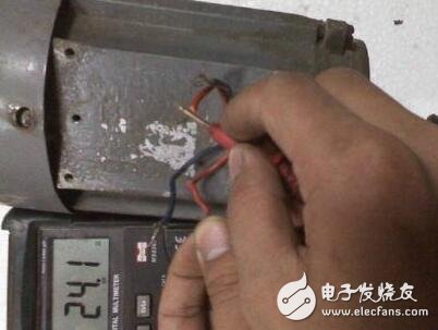
Single-phase motor is reversed and actual operationPrepare the multimeter. In order to facilitate the understanding of the operation, first separate the four leads in the motor junction box, and the capacitors are taken off temporarily.
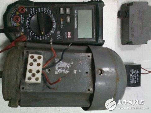
Turn the multimeter to the resistance position and measure which two wires are the main winding and which two are the secondary windings. We first measure the two lines with resistance (two blue lines) and remember the resistance.
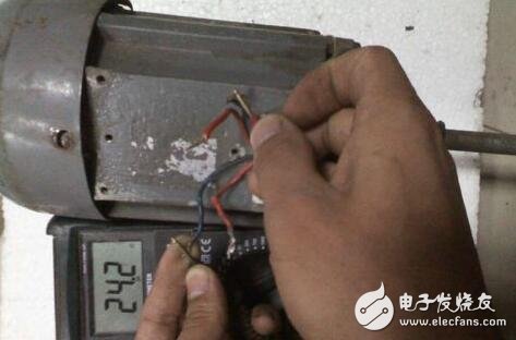
We then measure the resistance of the other two wires (two red wires). By comparison, the main resistance is small, and the resistance is large.
Shorten any of the red and blue lines together.
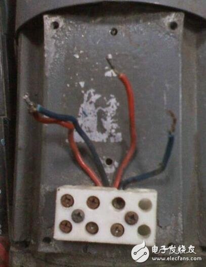
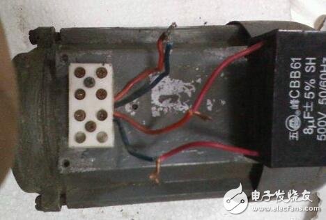
The other two wires are respectively connected to the two lead wires of the capacitor, and the capacitor is not positive or negative.
Connect the neutral wire (blue) of the power supply to the two wires that are shorted in "Step 4". The power line (red) is connected to one end of the capacitor. The power ground wire is connected to the motor casing. The turn of this connection is temporarily recorded as a forward rotation.
If you need to reverse the motor, simply connect the power line to the other end of the capacitor.
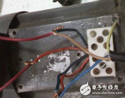
Note: The above is the explanation. If you need to power on, you must connect the wire to the terminal block and cover the junction box.
CAT6 Lan Cable performance is superior to iso11801-2002, TIA/EIA568C.2 and GB50311-2007, and it has passed the test of third-party authoritative institutions and obtained UL certification
Backward compatibility, downward-compatible CAT5e and lower categories of systems, to avoid user investment losses
Low transmission delay, compact cable design, reduce cable distortion and knotting during installation
The center PE cross frame ensures that the twisted pair is not damaged during the installation to the greatest extent, and has high anti-electromagnetic interference, so that the bit error rate of the transmitted signal is reduced to the lowest degree.
Built-in tearing rope, easy to construct.
Mark, cable number, cable class, cable gauge, fire rating, standard, meter number and lot number are printed on the outer sheath of cables.
The inner axle and outer carton are packed, and the outer carton is pasted with certificate of quality.
The production process of insulated single line adopts on-line control eccentricity, on-line spark detector, on-line water capacitance detector and other on-line equipment to ensure the high reliability and consistency of the products. The color code of insulated single line adopts color strip to meet the environmental protection requirements.
All materials made of copper, PE and PVC have been tested and analyzed, and the content of radioactive harmful heavy metals has been completely controlled within the strict international standards.
Insulation layer material is high density polyethylene (HDPE).
Different flame-retardant grades of materials can be used for outer sheath materials.

Cat6 Lan Cable,Cat6E Ethernet Cable,Flat Cat6 Ethernet Cable,Outdoor Lan Cable Cat6
Shenzhen Kingwire Electronics Co., Ltd. , https://www.kingwires.com