
Pulse Width Modulation Pulse Width Modulation (PWM) is an abbreviation of "Pulse Width ModulaTIon" in English. It is a very effective technique for controlling analog circuits by using the digital output of a microprocessor. It is widely used in From measurement, communication to power control and transformation in many areas.
Pulse width modulation is an analog control method that modulates the bias of the gate or base of a transistor according to the change of the corresponding load to realize the change of the on-time of the output transistor or transistor of the regulated power supply. The output voltage remains constant as operating conditions change, making it a very efficient technique for controlling the analog circuitry using the digital output of the microprocessor.
PWM control technology has become the most widely used control method of power electronics technology because of its simple control, flexibility and good dynamic response. It is also a research hotspot. Since the development of science and technology today has no boundaries between disciplines, combining modern control theory or implementing non-resonant soft-switching technology will become one of the main directions for the development of PWM control technology.
The basic principle of PWM (Pulse Width Modulation)
With the development of electronic technology, a variety of PWM technologies have emerged, including: phase voltage control PWM, pulse width PWM method, random PWM, SPWM method, line voltage control PWM, etc., and adopted in the nickel-hydrogen battery smart charger. Pulse width PWM method, which uses pulse trains with equal pulse widths as PWM waveforms. It can be frequency-modulated by changing the period of the pulse train. The width or duty cycle of the pulse can be adjusted. The voltage can be adjusted by appropriate control methods. Coordinate with frequency changes. The purpose of controlling the charging current can be achieved by adjusting the period of the PWM and the duty cycle of the PWM.
Pulse Width Modulation (PWM) is a method of digitally encoding analog signal levels. With the use of a high resolution counter, the duty cycle of the square wave is modulated to encode the level of a particular analog signal. The PWM signal is still digital because at any given time, the full-scale DC supply is either fully (ON) or completely OFF. The voltage or current source is applied to the analog load in a repeating pulse sequence of ON or OFF. When the DC power is applied to the load, the power supply is disconnected when it is disconnected. Any analog value can be encoded using PWM as long as the bandwidth is sufficient. Pulse Width Modulation (PWM) is a method of digitally encoding analog signal levels. With the use of a high resolution counter, the duty cycle of the square wave is modulated to encode the level of a particular analog signal.
The PWM signal is still digital because at any given time, the full-scale DC supply is either fully (ON) or completely OFF. The voltage or current source is applied to the analog load in a repeating pulse sequence of ON or OFF. When the DC power is applied to the load, the power supply is disconnected when it is disconnected. Any analog value can be encoded using PWM as long as the bandwidth is sufficient.
PWM (Pulse Width Modulation) basic control principle
PWM (Pulse Width ModulaTIon) control - Pulse width modulation technique that equivalently obtains the desired waveform (including shape and amplitude) by modulating the width of a series of pulses.
PWM control technology is the most widely used in inverter circuits. Most of the inverter circuits used are PWM type. PWM control technology relies on the application in inverter circuit to determine its importance in power electronics technology. status.
Theoretical basis:
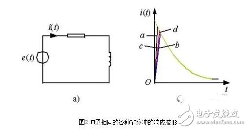
When narrow pulses of equal impulse and different shapes are applied to the link with inertia, the effect is basically the same. Impulse refers to the area of ​​a narrow pulse. The effect is basically the same, which means that the output response waveform of the link is basically the same. The low frequency bands are very close and only slightly different in the high frequency bands.

Area equivalent principle:
The narrow pulse of voltage as shown in Fig. 1 is applied to the first-order inertia link (RL circuit), as shown in Fig. 2a. The response waveform of its output current i(t) for different narrow pulses is shown in Figure 2b. As can be seen from the waveform, the shape of i(t) is slightly different in the rising section of i(t), but the falling sections are almost identical. The narrower the pulse, the smaller the difference in the response waveform of each i(t). If the above pulses are applied periodically, the response i(t) is also periodic. After decomposing with Fourier series, it can be seen that the characteristics of each i(t) in the low frequency band will be very close, only different in the high frequency band.
Replace a sine half-wave with a series of equal-width unequal pulses. The sine half-wave N is equally divided into N connected pulse sequences with equal widths but different amplitudes; instead of rectangular pulses, equal amplitude, The width is not equal, the midpoints coincide, the area (impulse) is equal, and the width changes according to the sine law.
SPWM waveform - A PWM waveform with a pulse width that varies in sinusoidal order and is equivalent to a sine wave.
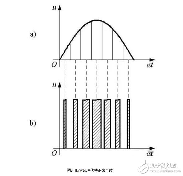
To change the amplitude of the equivalent output sine wave, change the pulse width by the same ratio.
PWM current wave: The current type inverter circuit performs PWM control, and the PWM current wave is obtained.
PWM waveforms are equivalent to various waveforms:
DC chopper circuit: equivalent DC waveform
SPWM wave: equivalent sinusoidal waveform, can also be equivalent to other required waveforms, such as equivalent non-sinusoidal AC waveforms, the basic principle is the same as SPWM control, and based on the equivalent area principle.
With the development of electronic technology, a variety of PWM technologies have emerged, including: phase voltage control PWM, pulse width PWM method, random PWM, SPWM method, line voltage control PWM, etc., and this paper introduces intelligent charging in NiMH batteries. The pulse width PWM method used in the device. It uses the pulse train with equal pulse width as the PWM waveform. It can be adjusted by changing the period of the pulse train. The width or duty cycle of the pulse can be adjusted. The voltage and frequency can be coordinated by appropriate control methods. The purpose of controlling the charging current can be achieved by adjusting the period of the PWM and the duty cycle of the PWM.
PWM classification
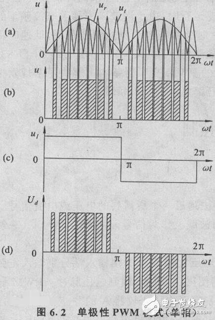
From the perspective of the polarity of the modulation pulse, PWM can be divided into two types: unipolar and bipolar control modes.
The basic principle of generating a unipolar PWM mode is shown in Figure 6.2. First, the triangle wave carrier signal ut of the same polarity. Compared with the modulation signal ur (Fig. 6.2(a)), a unipolar PWM pulse is generated (Fig. 6.2(b)); then the unipolar PWM pulse signal is compared with the inverted signal shown in Fig. 6.2(c) The UI is multiplied to obtain a positive and negative half-wave symmetric PWM pulse signal Ud, as shown in Figure 6.2(d).
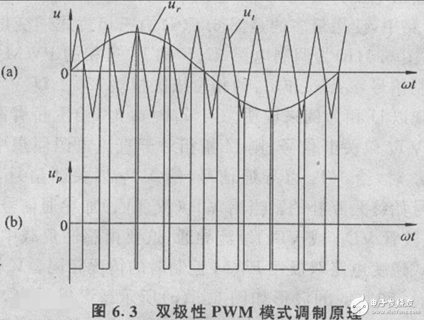
The bipolar PWM control mode uses a positive and negative alternating bipolar triangular carrier ut and a modulated wave ur, as shown in Figure 6.3, which can directly obtain a bipolar PWM pulse by comparing ut with ur. An inverter circuit is required.
PWM application
PWM software method to control charging current
The basic idea of ​​this method is to use the PWM port of the single-chip microcomputer to adjust the duty cycle of the PWM to adjust the duty cycle of the PWM to adjust the charging current without changing the PWM square wave period. The MCU required by this method must have two necessary conditions of ADC port and PWM port. In addition, the number of bits of the ADC is as high as possible, and the working speed of the MCU is as fast as possible. Before adjusting the charging current, the MCU first quickly reads the charging current, and then compares the set charging current with the actually read charging current. If the actual current is too small, adjust the PWM to the direction of increasing the charging current. Air ratio; if the actual current is too large, adjust the duty cycle of the PWM to the direction of decreasing the charging current. In the adjustment process of the software PWM, attention should be paid to the ripple interference introduced by the reading deviation of the ADC and the working voltage of the power supply, and the digital filtering technique such as the arithmetic average method is reasonably adopted. The software PWM method has the following advantages and disadvantages.
advantage:
Simplifies the hardware circuit of the PWM and reduces the cost of the hardware. Using software PWM without external hardware PWM and voltage comparator, only power MOSFET, freewheeling core, storage capacitor and other components are needed, which greatly simplifies the peripheral circuit.
The size of the turbulence can be controlled. In the process of PWM control charging, the MCU can detect the charging current on the ADC port in real time, and compare the charging current with the set turbulence to determine the adjustment direction of the PWM duty cycle.
The battery wakes up and charges. The MCU can use the ADC port and the PWM register to set the charging current arbitrarily. Therefore, for a battery with a relatively low battery voltage, after power-on, a small current can be charged for a period of time to charge the battery, and at a low current. In the case of a constant current, the impact damage to the battery is also small.
Disadvantages:
The current control accuracy is low. The sensing of the magnitude of the charging current is realized by the current sampling resistor. The voltage drop across the sampling resistor is transmitted to the ADC input port of the microcontroller. The microcontroller can read the voltage of the port to know the charging current. If the sampling resistor is set to Rsample (in Ω), the voltage drop of the sampling resistor is Vsample (in mV), and the reference voltage of the 10-bit ADC is 5.0V. Then, the voltage corresponding to 1 LSB of the ADC is 5000mV/1024≈5mV. A 5mV value is converted to a current value of 50mA, so the software PWM current control accuracy is up to 50mA. If you want to increase the current control accuracy of the software PWM, you can try to reduce the reference voltage of the ADC or the microcontroller with more than 10 bits of ADC.
The PWM uses a soft start method. During the process of high-current fast charging, during the charging from stop to restart, due to the existence of back electromotive force on the core, the effective duty cycle of PWM must be reduced during recharging to overcome the PWM adjustment due to software. The speed is slow and the problem of uncontrollable charging current is brought about.
Charging efficiency is not very high. In the fast charging, because the charging soft start is adopted, and the PWM adjustment speed of the single chip microcomputer is relatively slow, the time for actually stopping the charging or the small current slow rising charging is relatively large.
In order to overcome the problem of low charging efficiency caused by the disadvantages of 2 and 3, we can use a charging method with a longer charging time and a shorter charging time, such as charging for 2s for 50ms, plus slow start of current during soft start. The stop charging time of the combination is set to 50ms, and the actual charging efficiency is (2000ms-100ms)/2000ms=95%, which can also ensure the charging efficiency is above 90%.
Pure hardware PWM method to control charging current
Since the operating frequency of the single-chip microcomputer is generally around 4MHz, the operating frequency of the PWM generated by the single-chip microcomputer is very low, and the time required for the single-chip microcomputer to read the charging current by the ADC method, so the frequency of the charging current is adjusted by the software PWM method. It is relatively low. In order to overcome the above defects, an external high-speed PWM method can be used to control the charging current. Now the PWM control chip used in the smart charger mainly has TL494, etc. The working frequency of the PWM control chip can reach more than 300kHz, and the RC component can realize the constant current limiting function during the charging process of the battery. A normal I/O port control TL494 is enabled. Alternatively, a voltage comparator can be used instead of the TL494, such as the LM393 and LM358. The use of pure hardware PWM has the following advantages and disadvantages.
advantage:
High current accuracy. The control accuracy of the charging current is only related to the accuracy of the current sampling resistor, and has nothing to do with the microcontroller. It is not limited by the adjustment speed of the software PWM and the accuracy of the ADC.
High charging efficiency. There is no slow start problem with software PWM, so the energy charged into the battery is high during the same constant current charging and the same charging time.
Damage to the battery is small. Since the current during charging is relatively stable and the fluctuation amplitude is small, the impact on the battery is small, and the TL494 also has a voltage limiting effect, which can well protect the battery.
Disadvantages:
The price of the hardware is more expensive. The use of TL494 brings the above advantages while increasing the cost of the product, which can be overcome by means of LM358 or LM393.
Turbulence control is simple and pulsating. After the battery is charged, the battery is generally charged by trickle charging to overcome the capacity loss caused by the self-discharge effect of the battery. The ordinary I/O control port of the single-chip microcomputer cannot realize the function of the PWM port. Even if the simple PWM function can be realized by the software simulation method, the PWM frequency of the software simulation is relatively low due to the real-time requirement of the single-chip operation, so the final adoption is adopted. It is also a way of pulse charging, for example charging at 10% of the time and not charging for another 90% of the time. This has less impact on a fully charged battery.
Microcontroller PWM control port and hardware PWM fusion
For the pulsation problem of trickle charge of pure hardware PWM, a single-chip microcomputer with a PWM port can be used, and the pulsation of turbulence can be solved by combining an external PWM chip.
During the charging process, the charging current can be controlled in such a way that when the constant current and large current are used for rapid charging, the PWM output of the single chip microcomputer can be all high level (PWM control chip high level enable) or low level (PWM control chip low power) When enabled for trickle charge, the PWM control port of the microcontroller can be outputted with a PWM signal, and then the duty cycle of the PWM can be adjusted by testing the voltage drop across the current sense resistor until it meets the requirements.
PWM generally uses a voltage-controlled inverter, which changes the frequency of the inverter output waveform by changing the time during which the power transistors are alternately turned on, changing the on-off time ratio of the transistors in each half cycle, that is, by changing the pulse width. Change the size of the inverter output voltage sub value.
The rectifying portion and the inverting portion are substantially symmetrical.
In short, the final output waveform is adjustable, the secondary value is adjustable, and even the power factor is adjustable. However, it seems that the sine wave is used as the fundamental wave.
Analog circuit
The value of the analog signal can be continuously varied, and the resolution of its time and amplitude is not limited. A 9V battery is an analog device because its output voltage is not exactly equal to 9V, but changes over time and can take any real value. Similarly, the current drawn from the battery is not limited to a range of possible values. The difference between an analog signal and a digital signal is that the latter value can usually only belong to a predetermined set of possible values, for example, in the set of {0V, 5V}.
Analog voltage and current can be used directly for control, such as controlling the volume of a car radio. In a simple analog radio, the volume knob is connected to a variable resistor. When the knob is turned, the resistance value becomes larger or smaller; the current flowing through this resistor also increases or decreases, thereby changing the current value of the driving speaker, so that the volume is correspondingly larger or smaller. Like the radio, the output of the analog circuit is linearly proportional to the input.
Although analog control may seem intuitive and simple, it is not always very economical or feasible. One of the points is that analog circuits are prone to drift over time and are therefore difficult to adjust. Precision analog circuits that can solve this problem can be very large, bulky (such as old-fashioned home stereo equipment) and expensive. Analog circuits can also be severely hot, and their power consumption is proportional to the product of the voltage and current across the operating element. Analog circuits can also be sensitive to noise, and any disturbance or noise will definitely change the value of the current.
digital control
By digitally controlling the analog circuitry, the cost and power consumption of the system can be drastically reduced. In addition, many microcontrollers and DSPs already include a PWM controller on the chip, which makes digital control easier to implement.
In short, PWM is a method of digitally encoding analog signal levels. With the use of a high resolution counter, the duty cycle of the square wave is modulated to encode the level of a particular analog signal. The PWM signal is still digital because at any given time, the full-scale DC supply is either fully (ON) or completely OFF. The voltage or current source is applied to the analog load in a repeating pulse sequence of ON or OFF. When the DC power is applied to the load, the power supply is disconnected when it is disconnected. Any analog value can be encoded using PWM as long as the bandwidth is sufficient.
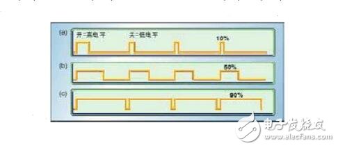
Figure 1 shows three different PWM signals. Figure 1a shows a PWM output with a 10% duty cycle, that is, 10% of the time pass in the signal cycle and the remaining 90% of the time is broken. Figure 1b and Figure 1c show the PWM outputs with duty cycles of 50% and 90%, respectively. The three PWM outputs are encoded with three different analog signal values ​​of 10%, 50%, and 90% of the full scale value. For example, suppose the power supply is 9V and the duty cycle is 10%, which corresponds to an analog signal with an amplitude of 0.9V.
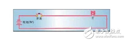
Figure 2 is a simple circuit that can be driven using PWM. The figure uses a 9V battery to power an incandescent bulb. If the switch that connects the battery and the lamp is closed for 50ms, the lamp will receive 9V during this time. If the switch is turned off during the next 50ms, the lamp will receive 0V. If this process is repeated 10 times in 1 second, the lamp will illuminate as if it were connected to a 4.5V battery (50% of 9V). In this case, the duty ratio is 50% and the modulation frequency is 10 Hz.
Most loads (whether inductive or capacitive) require a modulation frequency higher than 10 Hz. Imagine if the bulb is turned on for 5 seconds and then off for 5 seconds, then turned on and then off... The duty cycle is still 50%, but the bulb will illuminate within the first 5 seconds and will go out within the next 5 seconds. In order for the bulb to achieve a 4.5V voltage supply, the on-off cycle must be short enough compared to the response time of the load to the switch state change. To get the effect of the dimming light (but staying lit), the modulation frequency must be increased. The same requirements apply to other PWM applications. Usually the modulation frequency is between 1 kHz and 200 kHz.
Hardware controller
Many microcontrollers contain a PWM controller inside. For example, Microchip's PIC16C67 contains two PWM controllers, each of which can be selected for the on-time and period. The duty cycle is the ratio of the on time to the period; the modulation frequency is the reciprocal of the period. Before performing a PWM operation, this microprocessor requires the following work in software:
* Set the period of the on-chip timer/counter that provides the modulation square wave
* Set the on time in the PWM control register
* Set the direction of the PWM output. This output is a general purpose I/O pin.
* Start timer
* Enable PWM controller
Although the specific PWM controllers will differ in programming details, their basic ideas are usually the same.
Communication and control
One advantage of PWM is that the signals from the processor to the controlled system are digital and do not require digital to analog conversion. Keeping the signal in digital form minimizes the effects of noise. The noise can only be affected when the noise is strong enough to change logic 1 to logic 0 or logic 0 to logic 1.
The enhancement of noise resistance is another advantage of PWM over analog control, and this is the main reason why PWM is used for communication at some point. Switching from analog to PWM can greatly extend the communication distance. At the receiving end, the modulated high frequency square wave can be filtered out and restored to an analog form via an appropriate RC or LC network.
PWM is widely used in a variety of systems. As a concrete example, let us examine a brake controlled by PWM. Simply put, a brake is a device that grips something. Many brakes use an analog input signal to control the amount of clamping pressure (or braking power). The greater the voltage or current applied to the brake, the greater the pressure generated by the brake.
The output of the PWM controller can be connected to a switch between the power supply and the brake. To generate more braking power, simply increase the duty cycle of the PWM output through software. If a specific magnitude of brake pressure is to be generated, a mathematical relationship between duty cycle and pressure needs to be determined by measurement (the resulting formula or look-up table can be transformed to control temperature, surface wear, etc.).
For example, suppose you want to set the pressure on the brake to 100 psi, the software will do a reverse lookup to determine what the duty cycle should produce the pressure of this size. Then set the PWM duty cycle to this new value and the brake responds accordingly. If there is a sensor in the system, the duty cycle can be adjusted by closed loop control until the required pressure is accurately produced.
In short, PWM is economical, space-saving, and anti-noise performance. It is an effective technology that many engineers need to use in many design applications.
Nanning Nuoxin Technology Co., LTD , https://www.nx-vapes.com