introduction
Like other portable electronic products, the blood flow parameter detector should be small, slim, durable, reliable, and have a long standby time. Power management is to reduce the energy consumption of the system during idle time and maximize the effective energy supply rate of the embedded system, thereby extending the battery Power Supply time. In order to extend battery life, in the field of hardware, low-power hardware circuit design methods have been widely used. However, it is still not enough to use low-power hardware circuits. In the system design, the concept of "dynamic power management" is proposed, which is to turn off the components that are not in use in the system or enter a low-power mode (standby mode). Another more effective method is dynamic variable voltage DVS and dynamic variable frequency DFS, that is, dynamically adjust the CPU frequency or voltage during operation. This can maximize the effective energy supply rate on the premise of satisfying the instantaneous performance.
1 System design
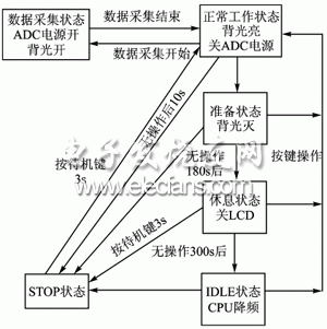
The whole instrument design uses S3C44B0 chip and uClinux operating system. The S3C44B0 chip is a mid-range product with many applications in the industry, low power consumption, and low cost. It provides five working states: NORMAL, SLOW, IDLE, STOP and SL_IDLE [1]. The system works normally in the NORMAL state. When the user has no operation period greater than a certain threshold, it enters the IDLE state, and the user presses the fake shutdown key to enter the STOP state. At this time, the system power consumption is very low. In order to facilitate management, the application layer has made a detailed division of the power management state and introduced six states of power management: data collection state, normal working state, preparation state, rest state, IDLE state and STOP state. Among them, IDLE state and STOP state are the same as the content provided by the chip, and the application program is responsible for the state transition. The components with the largest power consumption of the entire instrument are the backlight (EL backlight and keyboard LED), LCD and sensor driver, followed by the CPU, and the power management state transition is shown in Figure 1.

Figure 1 System power management state transition
1.1 Power management model
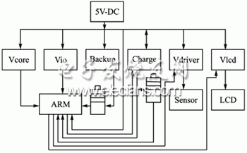
Figure 2 is a functional block diagram of power management, which contains 6 modules: Vcore, Vio, Backup, Charge, Vdriver and Vlcd, which provide power for each part of the system.

Figure 2 System power management block diagram
Vcore powers the system core with a power supply voltage of 1.8 V; Vio powers the system's I / O ports with a power supply voltage of 3.3V; Backup powers the system backup battery with a battery voltage of 3 V; Charge is a charging circuit with a battery voltage of 3.6 V rechargeable battery; Vdriver is the sensor power supply circuit, the voltage is ± 5 V; Vlcd is the LCD module power supply, the power supply voltage is 3.3V and 200VCA.
The battery charging circuit principle is: when the CPU detects that there is an external power supply, the CPU uses the ADC to detect the voltage at the two terminals of the battery and determines whether charging is required; when the voltage at both ends of the battery is lower than the set value, the Charge circuit is opened to charge the battery And detect the charging current to ensure the safe and effective charging of the battery. When the charging reaches the set value, the charging is stopped; when there is no external power supply, the battery supplies power to the entire system. The CPU detects the battery voltage and decides when it falls below a certain set voltage The alarm is still off to protect the battery.
Vcore and Vio power the system's core and I / O ports, respectively, and Vio also powers the memory. Backup battery is the backup battery of the system.
Vdriver provides the sensor with a voltage of ± 5 V and guarantees a current of 25 ± 1 mA.
Vlcd provides two sets of voltages for the LCD module, of which 3.3 V provides voltage for the LCD display and 200VAC provides voltage for the LCD backlight.
ZhenHuan's constant voltage mode Dimmable Led Driver use metal Iron material housing with junction box, IP20 level for indoor use only, accepts the output power range from max 100 Watts. The series led power transformer adopts 120V 60Hz input voltage and designed to meet UL/CUL Class 2 listed style enclosures, 5 years warranty.
120V Input Indoor Rated Dimmable Led Driver
Light Fixture Drivers,Dimmable Led Landscape Lighting Drivers,Commercial Lighting Dimmers Drivers,Indoor Low Voltage Lighting Transformer
Shenzhenshi Zhenhuan Electronic Co Ltd , https://www.szzhpower.com
