The servo motor is a traditional motor. It is the actuator of an automatic device. The biggest feature of servo motor is controllable. When there is a control signal, the servo motor rotates, and the speed is proportional to the size of the control voltage. After removing the control voltage, the servo motor will stop rotating immediately. Servo motors are widely used, and almost all automatic control systems are needed. In home appliance products, such as video cameras, CD players, etc. are indispensable important components.
1. Working principle of simple servo motor 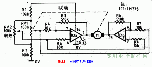
Figure 22 shows the simplest application of a servo motor. The potentiometer RV1 is driven by a servo motor. The motor can be any servo motor with a current not exceeding 700mA and a voltage of 12-24V. In the picture, RV1 and RV2 are connected as Wheatstone bridge. The integrated circuit LM378 is a dual 4-watt power amplifier, which also forms a motor-driven differential amplifier in a bridged manner.
When any change of RV2 will destroy the balance of the bridge, a differential voltage will be generated between RV1 and RV2, which will be amplified and sent to the motor. The motor will rotate and drag the potentiometer RV1 to a new position to bring the bridge back to a new balance. So, RV1 tracks the movement of RV2.
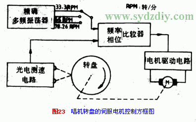
Figure 23 is a block diagram showing the principle of a speed sensor servo motor system that can be used for precise speed control of a turntable. The motor uses a traditional belt mechanism to drive the turntable. The edge of the turntable reflects the graphic structure of the article at equal intervals. Use photoelectric speedometer for monitoring and detection. The output signal of the photoelectric speedometer is proportional to the rotation speed of the turntable. Compare the phase and frequency of the output signal of the photoelectric speedometer with the phase and frequency of the standard oscillator, and use its error signal to control the motor drive circuit. Therefore, the rotation speed of the turntable is precisely maintained at the rated rotation speed. The shift of the rated speed can be controlled by the operation switch. These control circuits have been made into dedicated integrated circuits by manufacturers.
2. Digital proportional servo motor
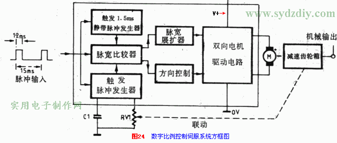
One of the best types of servo motors is a digital proportional remote control system. In fact, these devices are composed of three parts: the use of integrated circuits, servo motors, reduction gear box potentiometer mechanism. Figure 24 is a block diagram of such a system. The drive input of the circuit is driven by a pulse signal with a period of 15 ms and a pulse width of 1 to 2 ms. The width of the input pulse controls the position of the servo mechanical output. For example: 1ms pulse width, the position is on the far left; 1.5ms is in the middle, and 2ms is on the far right.
Each input pulse is transmitted simultaneously in three channels. Trigger a fixed pulse generator with a pulse width of 1.5ms all the way. One input triggers the pulse generator, and the third input is sent to the pulse width comparison circuit. Use the gear box output to RV1 to control the variable width pulse generator. After these three pulses are sent to the pulse width comparator at the same time, the direction of the motor drive circuit is determined all the way. The other way is sent to the pulse width expander to control the speed of the servo motor, so that RV1 quickly drives the mechanical position output to follow any changes in the input pulse width.
The above servo motor type is often used in multi-channel remote control systems. Fig. 25 shows a waveform diagram of the four-channel digital proportional control system.
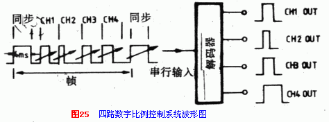
It can be seen from the figure that it is a serial data input, and the control signals of each channel are divided through the decoder. Each frame contains 4ms synchronization pulses, followed by four "sequence" pulses with variable width (1-2ms) in sequence. The decoder converts the four pulses into parallel form, which can be used to control the servo motor.
3. Digital servo motor circuit Digital servo motor control unit, you can buy ready-made integrated circuits. Such as ZN409CE or NE544N servo motor amplifier integrated circuit. Figures 26 and 27 show typical applications of these two integrated circuits.
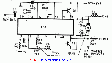
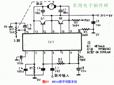
The element values ​​in the figure apply to the case where the input pulse width is 1 to 2 ms and the frame pulse width is approximately 18 ms.
Fig. 28 is a general-purpose test circuit suitable for the aforementioned servo motor type. The servo power battery is usually 5V. The input pulse is sent to the servo circuit through a standard servo socket. The width of the frame pulse is 13-28ms; it is adjusted and controlled by RV1. RV2 adjusts and controls the pulse width between 1-2ms. Use RV4 to fine-tune the intermediate value to 1.5ms. The output level is adjusted by RV3.
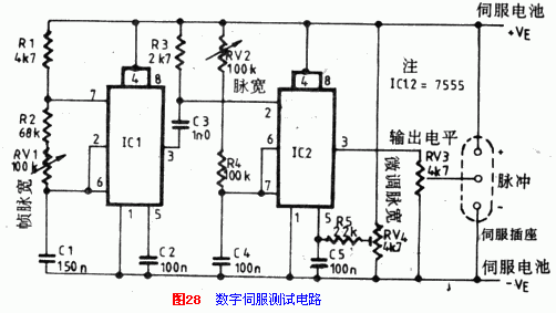
The two integrated circuits are of the time base circuit CMOS7555 type, and the power supply voltage can be as low as 3V and still work. IC1 is an unstable multivibrator, which generates frame time pulses, and its output triggers IC2. IC2 is a monostable circuit that generates output test pulses.
NTC temperature sensors from Feyvan electronics provide various choices for a wide range of applications and are available in custom engineered Thermistor Probe package configurations for a variety of mounting and connectivity options with low costs.
There are many options for you to choose as examples of no-encapsulated type, screw type, bullet type, film threading type, clamp type, medical equipment type, mirco-probe type, surface mounting type, flange type and cylinder type. Highly skilled R&D team, advanced manufacturing facilities, rigorous quality control and good after-sales service ensure all our products` excellent quality.
Ntc Sensor,Sensor Ntc,Thermistor Probe,Thermistor Temperature Sensor
Feyvan Electronics Technology Co., Ltd. , http://www.fv-cable-assembly.com
