LC-KING headphone amplifier circuit
For audiophiles, audiophile is equal to burning money. For some audiophiles who are not very economically comfortable, playing with headphones is a good best way to have a fever without too much money. The reason is very simple. Generally speaking, it is difficult to buy low-quality audio equipment on the market for two or three hundred dollars, but you can buy a very good pair of fever headphones, and the frequency response and various indicators of the headphones are not inferior to high-end ones. The speaker unit is also the main reason why the headphone amplifier DIY is popular at home and abroad. In the headphone amplifier, generally excellent discrete component circuits have been seen on many domestic and foreign websites, and they are made by electronic tubes, but for general enthusiasts. That is to say, it is difficult to find the components, and the matching of the tubes is also a headache. The difficulty of making the main transformer of the electronic tube has been solved.
At the request of netizens, I have found some easy-to-make headphone amplifier circuits for reference for those with better hands-on skills. The circuit diagrams are from domestic and foreign websites and electronic magazines. If there is a violation of your copyright, please notify me and I will delete it.
LC-KING A (A) headphone amplifier circuit

The picture above is a circuit diagram, the circuit is very simple, the front stage amplification push is NE5532 or other types of OP, U2A is DC SERVER, used to stabilize the potential of the midpoint, and the push level 2SD882 is an NPN type power triode, which works in the Class A state. Therefore, the amount of heat generated is large, and the current flowing through R11 and R31 can be adjusted by changing its resistance. The transistor should be added with a radiator during production.
LC-KING's class AB amplifier circuit
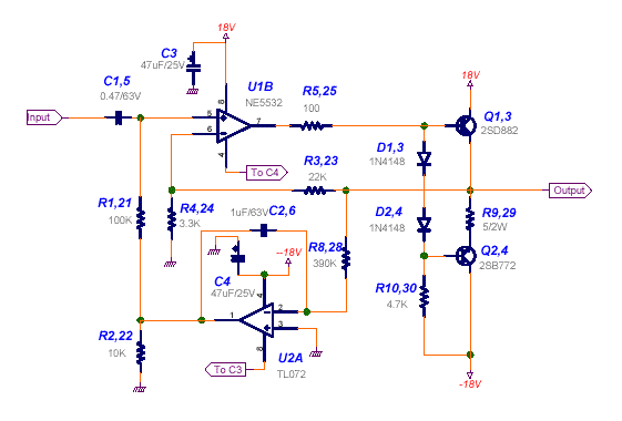
The picture above shows the class-A power amplifier circuit of LC-KING. The amplification of the latter stage consists of the pair of tubes 2SD882 (NPN) and 2SB772 (PNP) TL072 as DC servo circuits, which play a role in stabilizing the potential.
The amplification circuit of LC-KING is relatively simple, and it is not difficult to manufacture. It can be completed with a hole plate, and the transistor of the rear pole can also be replaced with other tubes. The power supply of the amplifier also has a great influence on the sound quality. Of course, the use of Watian power supply is very good. You can also use the servo power supply. The power supply of the original picture is a little complicated. The key is that some components are very biased, so they are not put on the Internet.
-------------------------------------------------- ------------------------
Ear amp made with dual op amps such as OPA2604
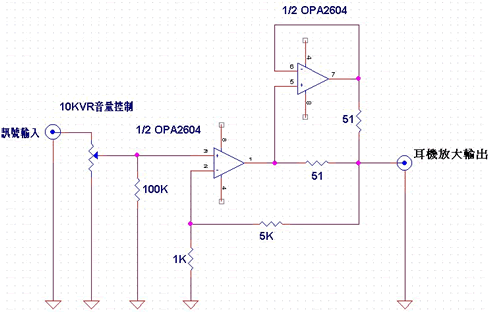
The picture above is a popular amp with an operational amplifier on the Internet. Of course, you can use other dual op amps to replace it to get different sounds. The use of two amplifiers in the picture above can improve the current output capability, which can promote High impedance headphones, most high-end headphones are high impedance. It is more popular to use OP234 or OP2134 (dual op amp) as the headphone amplifier on foreign websites, because the performance of the op amp is good when it is operated at low voltage, so that it can be conveniently powered by batteries. Make a portable amp.
ï¼ï¼ï¼ï¼ï¼ï¼ï¼ï¼ï¼ï¼ï¼ï¼ï¼ï¼ï¼ï¼ï¼ï¼ï¼ï¼ï¼ï¼ï¼ï¼ï¼ï¼ï¼ï¼ï¼ï¼ï¼ï¼ï¼ï¼ï¼ï¼ï¼ï¼ï¼ï¼ï¼ï¼
ZEN amp
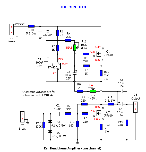
The above is the amp circuit of ZEN. It is also a circuit that the domestic enthusiasts are happy to make in recent years and are said to be used to practice listening to the ears. There are also PCB boards that are supplied online for assembly by enthusiasts. The author did not personally practice it. But there is a chance to find a component and want to give it a try.
-------------------------------------------------- --------------------------
MOSFET Class A amplifier


Follow WeChat

Download Audiophile APP

Follow the audiophile class
related suggestion
There are many reasons for the failure, and the situation is very complicated. Some are simple failures caused by one reason, and some are complicated failures caused by the interaction of multiple reasons ...
Although there are a large number of active monitor speakers (with built-in amplifier circuit) on the market, but here to remind you that the growth of the recording industry has been accompanied by passive monitoring ...

This article mainly introduces how to calculate the voltage amplification of the amplifier circuit (single-stage and multi-stage). When seeking the voltage amplification of discrete component multi-stage amplifier circuits ...

This article mainly introduces the complete circuit diagram of the electret microphone amplifier circuit (audio amplifier / microphone / microphone amplifier circuit diagram in detail). The working principle of electret microphone ...
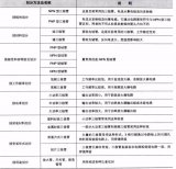
The compound triode is to select the triodes of various polarities to connect respectively.
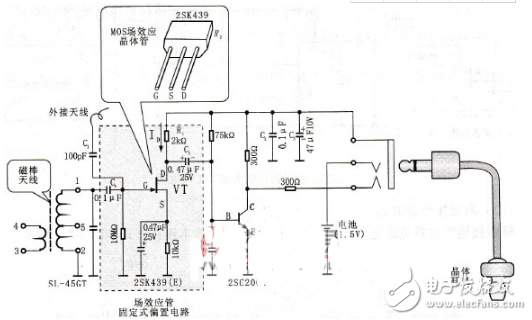
This article mainly introduces the complete circuit diagram of the field effect tube amplifier circuit (the detailed explanation of the five field effect tube amplifier circuit schematic diagrams). In this circuit, the battery acts as a DC power supply ...
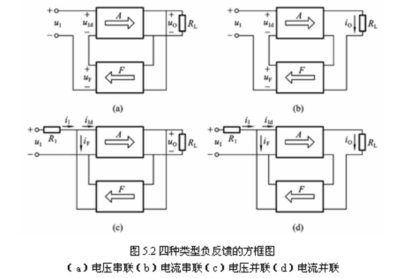
This article mainly introduces the negative feedback amplifier circuit diagram (five negative feedback amplifier circuit design schematics). If the feedback signal is taken from the output voltage signal, ...
The Op07 chip is a low-noise, non-chopped and stable bipolar op amp integrated circuit. Since OP07 has a very low input offset voltage ...
This article mainly introduces the simplest DC amplifier circuit diagram (the seven simplest DC amplifier circuit design schematics). Ability to amplify DC signals ...
This article has introduced the operational amplifier and the amplifier circuit in detail, including the principle of the operational amplifier, the classic operational amplifier circuit diagram and amplification ...
With the help of Multisim 10's simulation platform, this article uses Multisim simulation to analyze the resistance-capacitance coupled negative feedback amplifier circuit to study ...

The frequency of body surface ECG signals is mainly concentrated in 0.05 ~ 100Hz, the amplitude is 10μV ~ 4mV (typical value is 1mV) ...

When the random interference signal is mixed into the input signal, an analog filter can be used to filter out the useless components of the signal to improve the quality of the signal. But the analog filter ...

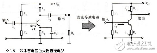
This article introduces the analysis of common-emitter, common-collection and common-base amplifier circuits in the DC path. The basic common-emitter amplifier circuit is shown in the figure, it should be encountered frequently in the analog book ...
Compared with Protel, Multisim 10 has a more intuitive human-computer interface. The resistance-capacitance coupling two-stage amplifier circuit is an analog ...

The amplification effect of the triode is: the collector current is controlled by the base current (assuming that the power supply can supply enough current to the collector), and the base ...

This article brings you five kinds of subtractor circuit design solutions.
With the continuous development of science and technology, laser ranging, microwave radar ranging, ultrasonic ranging and infrared ranging have emerged in the field of ranging. ...

Common collector amplifying circuits are often used as input stages and output stages of amplifiers or for impedance matching, and are widely used in practice. This article on co-collection ...

This article mainly introduces the equivalent model of the universal triode! Help you get all kinds of parameter analysis. The main components of the transistor amplifier circuit are pnp type, n ...
The core component of the amplifier circuit is a triode, so it is necessary to have a certain understanding of the triode. There are many types of amplifier circuits composed of transistors, and we often use ...
Amplification is the most basic analog signal processing function. It is realized through an amplifier circuit. Most analog electronic systems use different types of amplifiers ...

The amplifier circuit is also called an amplifier, which is one of the most widely used electronic circuits and the basic unit circuit that constitutes other electronic circuits. The so-called zoom ...
The amplifier circuit is also called an amplifier, which is one of the most widely used electronic circuits and the basic unit circuit that constitutes other electronic circuits. The so-called zoom, ...

The CD4069 chip is a six-inverter commonly used in digital circuits and single-chip systems. Its structure is relatively simple, with a total of six inverters, a total of ...

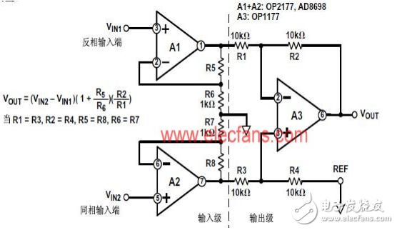
The double-ended input is also called differential input, and the double-ended input summing circuit is shown in Figure 1. The derivation method of its output voltage expression is in phase with the in-phase input arithmetic circuit ...
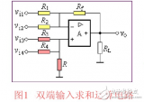
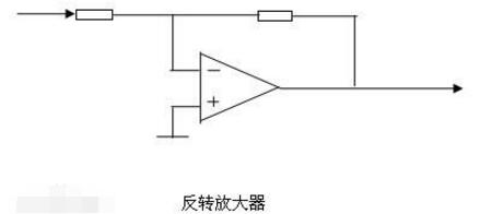
Inverting input operation circuit (proportional) The input signal is added to the inverting input terminal to introduce deep voltage and parallel negative feedback integrated op amp works in the linear region ...

Taking the common-emitter amplifier circuit as an example, the composition of the amplifier circuit is introduced. The role of each component in the circuit is introduced. Amplifier circuit input ...

The common point of the common-collection amplifier circuit and the common-emitter amplifier circuit is the input signal via the base. The output voltage (via the coupling capacitor) to the load through the collector is common shot ...
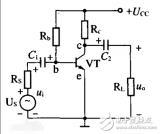
The amplifier circuit is also called an amplifier, which is one of the most widely used electronic circuits and the basic unit circuit that constitutes other electronic circuits. The so-called zoom, ...

Common-mode input resistance: This parameter represents the ratio of the input common-mode voltage range to the amount of change in the bias current within the range when the operational amplifier is operating in the linear region. in...
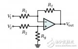
The single-ended output in the differential amplifier circuit is an output to ground, which is an unbalanced output, and the output terminal of the double-ended output can be floated. At this time, a balanced output can be formed. and also...
The concept of zero drift (zero drift) can be described as: when the input signal of the amplifier circuit is zero (that is, there is no AC input), due to temperature changes, the power supply ...

Analog amplifier circuits mainly include common-emitter, common-collector and common-base amplifiers are single-tube amplifiers, resistance-capacitance coupling, transformer coupling and direct coupling multi-stage amplifier circuits, ...

The AD603 controllable gain amplifier chip design is a high gain, high broadband DC amplifier, which uses a two-stage cascade amplifier circuit to increase the amplification ...

The amplifier circuit refers to a circuit capable of amplifying a weak signal. For example, the key component in a hearing aid is an amplifier. Amplifiers have AC amplifiers and ...
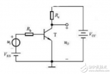
Comparison of three BJT amplifier circuits: common-shot amplifier circuit, both current and voltage can be amplified. Common collector amplifier circuit: only amplify the current, follow the voltage ...

Transistor, the full name should be semiconductor triode, also known as bipolar transistor, crystal triode, is a semiconductor device that controls the current, its role is to weaken ...

In electronic circuits, the object of amplification is the amount of change, and the commonly used test signal is a sine wave. The essence of amplification is under the action of the input signal, through the active element ...
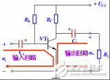
The basic amplifier circuit generally refers to an amplifier circuit composed of a triode and a field effect tube.

The negative feedback circuit is used in the amplifier, the purpose of which is to improve the working performance of the amplifier and improve the output signal quality of the amplifier.

After the introduction of negative feedback, the improvement of the amplification stability of the amplifier circuit is usually measured by the relative change.
Triode, the full name should be semiconductor triode, also called bipolar transistor, crystal triode, is a semiconductor device that controls the current, its role is to weaken ...

When the amplifier circuit amplifies the signal, there are always two electrodes as the input terminal of the signal, and there should also be two electrodes as the output terminal. According to the semiconductor triode ...

Triode, the full name should be semiconductor triode, also called bipolar transistor, crystal triode, is a semiconductor device that controls the current, its role is to weaken ...

The three configurations of the amplifying circuit are divided into common base, common set, and common launch three configurations. Amplifier circuits are usually transistors, field effect transistors, integrated operational amplifiers ...

The same as the transistor amplifier circuit introduced before, the connection between the FET amplifier circuits at all levels must also be connected through a capacitor to form a CR connection ...
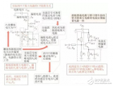
The core component of the amplifier circuit is a triode, so a certain understanding of the triode is required. There are many types of amplifier circuits composed of transistors, we often use ...

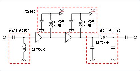
With the vigorous development of mobile data communication technology, the hardware and technical requirements of various wireless devices are becoming higher and higher, so under the realization of various communication environments ...
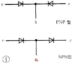
The triode is a semiconductor device that controls current. Its function is to amplify a weak signal into an electrical signal with a large amplitude value. It is also used as a contactless switch. turn off...
Bloggers are not "all-round champions" in all technical aspects, so this article is for your reference only. The purpose of the blogger's writing this article is to be able to play an important role ...
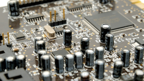
Amplification circuit (amplification circuit) is through a device (the core is triode, field effect tube) will be weak ...
The power saving switch introduced this time, in the daytime or when the light is bright, the power saving switch is turned off, the light is not turned on; at night or when the light is dark, the power saving switch is ready ...
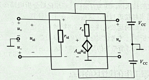
Operational amplifier is a familiar word for students studying engineering. As the most common analog device, operational amplifiers are widely used in signal ...
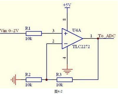
Changes in temperature seriously affect the static operating point. For the previous circuit (basic cascode amplifier circuit), the static operating point is determined by β and ICEO, ...
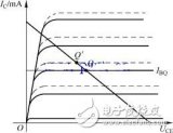
Abstract: Transistors are widely used in modern circuits. Their main functions are amplification and switching functions. This article focuses on the amplification of transistors ...
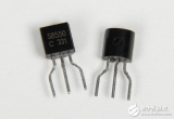
When the signal source is a constant voltage source or a voltage source with a small internal resistance, series negative feedback should be introduced, and when the signal source is a constant current source or a voltage source with a large internal resistance, ...
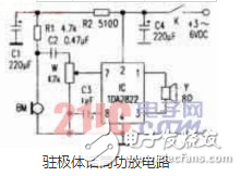
The microphone power amplifier circuit is made based on TDA2822, and a dual-channel audio amplifier integrated circuit is used. Its main features are high efficiency, low power consumption, static work ...
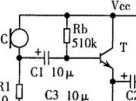
A number of important technical indicators of the amplifier circuit are closely related to the position of the static operating point. If the static operating point is unstable, some of the performance of the amplifier circuit is also ...
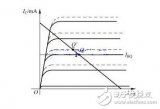
The mastery of analog circuits is divided into three levels. The primary level is to memorize these twenty circuits proficiently, and to understand the role of these twenty circuits. As long as it is an electronic hobby ...
The core component of the amplifier circuit is a triode, so a certain understanding of the triode is required. There are many types of amplifier circuits composed of transistors, we often use ...
In recent years, with the construction of modern high-voltage and ultra-high-voltage transmission networks, power systems are developing towards large-capacity, high-voltage, high-current ...

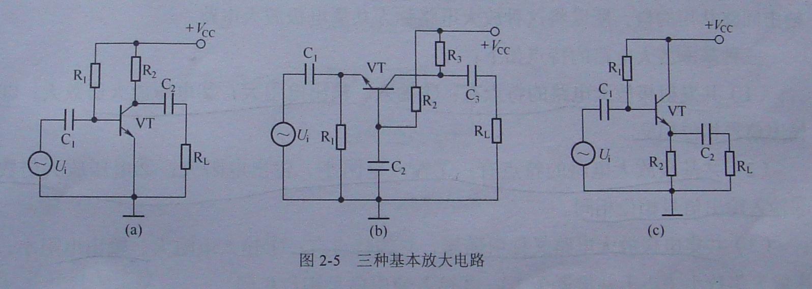
This article mainly introduces the three simplest triode amplifier circuits

The core component of the amplifier circuit is a triode, so a certain understanding of the triode is required. There are many types of amplifier circuits composed of transistors, we often use ...
Generally, the greater the depth of feedback, the better the improvement of the circuit performance, such as improved gain stability, widening of the passband, reduction of nonlinear distortion, input ...
The "unused op amp" we are talking about here does not refer to the op amp in the chip storage box or anti-static bag; it refers to the same package ...

Hearing aids are tools, equipment, devices, and instruments that help hearing-impaired people improve their hearing impairment and thus improve their ability to communicate with others.

Because modern compact devices integrate more performance and functions into smaller packages, it becomes more important to manage the heat dissipation in electronic products. even if...
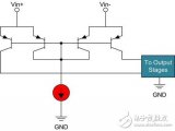
With the continuous development of computer technology, teaching methods will become increasingly rich and diverse. The experiments and functional demonstrations that must be completed in the laboratory ...
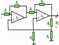
The classic four-resistor difference amplifier seems simple, but its performance in the circuit is not good. Starting from the actual production design, this article discusses the discrete resistance, ...
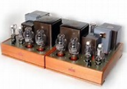
The analog circuit is an electronic circuit that processes analog signals. Analog signals are signals with continuous time and amplitude (continuous means that it can be within a certain value range ...

A current-sense amplifier with a wide common-mode input range. The MAX44284 current-sense amplifier combines high accuracy and a wide input common-mode range. ...
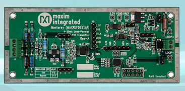
The multivibrator composed of 555 timers is shown in Figure 3. RA, RB and C are external timing components, and the high-level trigger terminal (6 feet) will be in the circuit ...
The old-fashioned stethoscope has no amplification effect, the sound is weak, it is very uncomfortable to plug in the ear, it cannot isolate the environmental noise, and the frequency response is not adjustable. This article proposes ...

The fully differential instrumentation amplifier has the advantages that other single-ended output amplifiers do not have. It has strong common mode noise source anti-interference, which can reduce the second harmonic loss ...
Add a resistor to match the input DC resistance of the op amp circuit? Please see the circuit shown below. Many of us would dogmatically believe that Tim ...

In practical applications, it is necessary to deal with increasing radio frequency interference (RFI), especially for the case of long signal transmission lines and low signal strength ...
CMX638 is a voice encoding and decoding chip dedicated to communication systems, explaining the basic structure and function of CMX638, and giving a C-based ...

Attenuation-feedback tone control circuit composed of transistor and RC network. In the circuit, RPz is the bass control potentiometer, RP3 is the treble control electric ...

The STM32F103VET single-chip microcomputer of the main control module is the core of the controller. The single-chip microcomputer is a 32-bit high performance produced by ST STMicroelectronics ...

This small system takes SPCE061A single chip as the core, the peripheral circuit includes: 4 × 4 keyboard, the infrared keyboard used in this system is RM-20 ...
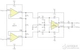
This design example provides two simple, inexpensive drivers for headphones and audio lines, as shown. These two drives are designed for electric guitars and violins, ...

Due to the use of AC negative feedback, the theoretical analysis of the DC working state of the circuit after joining the feedback network should remain unchanged. At Protel 99 s ...
The depth of the ocean is an important parameter of ocean water. Knowing the depth of the ocean can prevent ships sailing on the sea from stranding and hitting the reef. Submarine activities on the seabed ...

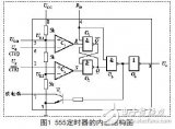
The popular 555 timer can be used as a PWM / D amplifier for musical instruments or other applications. It can be in the range of 4.5V ~ 16V power supply voltage ...

A new electrocardiograph system based on GPRS standard is proposed. The system consists of monitoring terminal (portable ECG monitor), wireless network and monitoring ...
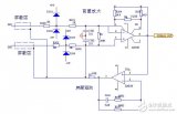
The picture shows a broadband amplifier circuit using negative feedback. The amplifiers of this circuit adopt transformer coupling, and the amplification part uses field effect transistors and ...

This circuit is a simple recording circuit with a simple recording circuit that is small, power-saving, and does not require magnetic tape.
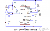
The alarm can detect the infrared rays emitted by the human body. When a person enters the monitoring area of ​​the alarm, the alarm sound can be issued, which is suitable for home, office, warehouse ...

MOSO UFO High Bay LED Driver have the character of high power factor, high efficiency, high reliability and high-precision constant current. The UFO led driver owns a complete of function, various specifications can meet more different parameter of customers` requirement.
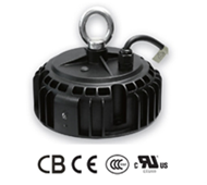
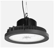
MOSO Intelligent innovator UFO shape led power has the led driver industry ' s unique derating over temperature protection circuit , which can make the light power supply not easy suddenly happen the phenomenon of over - temperature and shutdown even under the harsh working environment , so as to ensure continuous illumination.
The efficiency of the led driver supply is high and the power consumption is small. Accordingly, the heat in the lamp is small, then it reduce the temperature rise of the lamp. It is more advantage to delay the light decay of LED.
This Circular high-bay lighting drivers creatively integrated limited power, 0~10V/PWM dimming, dali control is optional.
Dali Industrial Light LED Driver complied with CCC/CE/ENEC/UL/SAA/CB safety regulations. Surge immunity is DM-4KV,CM-6KV.
High Bay LED Driver,Waterproof High Bay LED Driver,Modern High Bay LED Driver,UFO High Bay LED Driver
Moso Electronics , https://www.mosoleddriver.com
