1. Buck converter: The output voltage is less than the input voltage.
2. Series switching power supply: Single-pole double-throw switch (transistor) is connected in series between input and output.
3. Three-terminal switch type step-down power supply:
1) A line of input and output is common.
2) The output voltage is less than the input voltage.
2, Buck converter working principle structure diagram
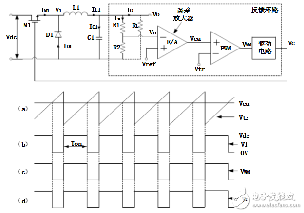
Figure 1. Basic schematic of the Buck converter
As can be seen from the above figure, the Buck converter mainly includes: a switching element M1, a diode D1, an inductor L1, a capacitor C1 and a feedback loop. The general feedback loop is composed of four parts: sampling network, error amplifier (Error Amplifier, E/A), pulse width modulator (PulseWidth ModulaTIon, PWM) and drive circuit.
3, Buck converter working process analysis
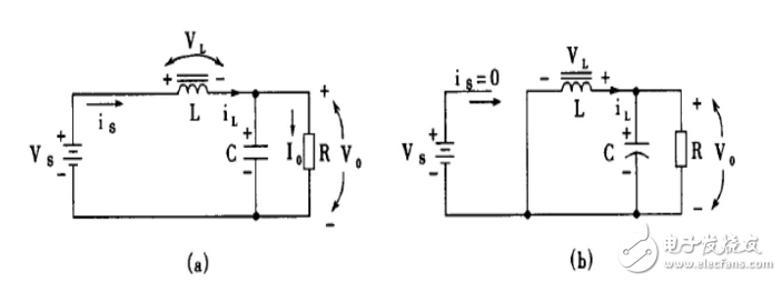
Figure 2. Working process of the Buck converter
In order to facilitate the analysis of the basic working principle of the Buck converter, we first make the following reasonable assumptions:
1) Both the switching element M1 and the diode D1 are ideal elements. They can be turned on and off quickly, and the voltage drop is zero when turned on, and the leakage current is zero when turned off;
2) Capacitors and inductors are also ideal components. When the inductor operates in the linear region and is not saturated, the parasitic resistance is equal to zero. The Equivalent Series Resistance (ESR) and Equivalent Series Inductance (ESL) of the capacitor are equal to zero;
3) The ripple voltage in the output voltage is very small compared to the output voltage and can be ignored.
4) The impedance of the sampling networks R1 and R2 is so large that the current flowing through them is negligible.
Based on the above assumptions, we will analyze the working process of the Buck converter.
As shown in FIG. 1, when the switching element M1 is turned on, the voltage V1 is equal to the output voltage Vdc, and the transistor D1 is in the reverse-off state, and the current is 01  DI. Current 11LMII flows through inductor L1 and the current increases linearly. After being filtered by the capacitor C1, an output current OI and an output voltage OV are generated. The sampling networks R1 and R2 sample the output voltage OV to obtain a voltage signal SV, and are amplified to obtain a signal in comparison with the reference voltage refV. As shown in Fig. 1(a), the signal eaV is compared with the linearly rising triangular wave signal trV. When eatrVV, the control signals WMV and GV jump to low, and the switching element M1 is turned off. At this time, in order to keep the current 1LI unchanged, the magnetic field in the inductor L1 will change the polarity of the voltage across the inductor L1. At this time, the diode D1 is forward biased and has a current 1DI flowing, so that D1 is called a freewheeling diode. If OLII  1, the capacitor C1 is in a discharging state, which is favorable for the output current OI and the output voltage OV to be constant. The state in which the switching element is turned off is maintained until the beginning of the next cycle. When the condition treaVV is once again satisfied, the switching element M1 is turned on again, and the above process is repeated.
From the analysis, the working process of the Buck converter can be divided into two parts:
1) The switch (transistor) is turned on: the diode D1 is turned off; the inductor current is linearly increased and stored; the capacitor is charged and stored; and the output voltage is Vo.
2) Switch (transistor) is turned off: diode D1 is turned on; inductor releases energy; capacitor discharges; output Vo.
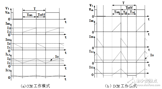
4, the two working modes of the Buck converterAccording to the inductor current 1LI starting from zero at the beginning of each cycle, the operating mode of the Buck converter can be divided into the inductor current continuous operation mode (ConTInuousConducTIonMode, CCM) and the inductor current discontinuous operation mode (DisconTInuousConductionMode, DCM). The main waveforms of the two modes of operation are shown in Figure 2.4. The following two working modes are analyzed separately.

Figure 4 The main working waveform of the Buck converter
Iget bar flavours has 13 differentce, the flavor of the iget bar is amazing and exotic, you can enjoy different flavours from Mango ice, blueberry ice to double apple etc. it's the upgrade vape in the iget brand vape, The main market is Australia, USA, Russia etc. The design of the iget bar incorporates Chinese elements, so it looks very nice and comfortable. With the large capacity of 12ml e-liquid and strong power of 1500Mah battery, the iget bar puffs is up to 3500puffs, which is double puffs compare to IGET Xxl! It seems it can work forever! The nic salt is 5%, apply for the vaping person demanded for the nic strength.
For the Iget Vape, besides iget bar 3500, there are iget legend, iget xxl 1800, iget shion, iget king, iget max and others, all of them are original that you can buy them without worried to buy a fake iget vape.
Iget Bar vape, iget bar flavours, iget bar 3500, iget bar vapes, iget bar price, iget bar puffs
Shenzhen Kate Technology Co., Ltd. , https://www.katevape.com
