
The slot array antenna is widely used on the seeker antenna due to its excellent electrical performance. In the antenna front of the usual seeker antenna, the array elements are evenly distributed. However, with the development of seeker technology, more and more seekers adopt composite seeker technology, such as dual microwave head composite seeker, microwave and millimeter wave composite seeker, RF and photoelectric composite guidance. Head and so on, you need to place multiple detectors on the same seeker. Particularly for optical seekers, the detector needs to be placed in the center of the composite seeker aperture, which presents a need for a single-pulse seeker antenna array with a central aperture. For the design of such a centrally apertured non-uniform antenna array, the traditional antenna pattern synthesis method is no longer applicable. To this end, this novel center-open single-pulse slot array antenna is specially designed and analyzed. The single-pulse slot array antenna used in the millimeter band can achieve higher gain.
2, antenna characteristics and design methods2.1 Directional pattern synthesis of non-uniform antenna fronts
After opening the hole in the center of the slot array antenna, the problem is that the excitation distribution of the antenna port surface changes. For an antenna face with a uniform excitation distribution, the side lobes of the antenna array factor are -13 dB. If you want to get the low side lobes, you can use the weighting method of the antenna array to carry out the pattern synthesis. The weighting method of the uniform array is the Taylor distribution method and the Chebyshev method, etc., and the characteristics are that the center of the mouth is the largest, and the direction toward the edge is gradually smaller. However, when the center of the antenna array is opened, there is no maximum excitation, and the antenna side lobes of the antenna array will rise rapidly. Figure 1 is a uniform array circular surface excitation distribution of 316 elements with a weighted side lobes of -26 dB using the Taylor distribution method. Figure 2 is a circular surface of a non-uniform array with 4*4 array elements removed from the center of the array. Incentive distribution.
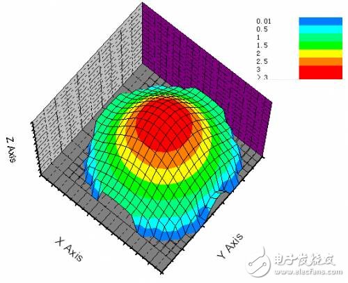
Fig.1 Schematic diagram of the excitation distribution of the -26dB uniform weighted sidelobe
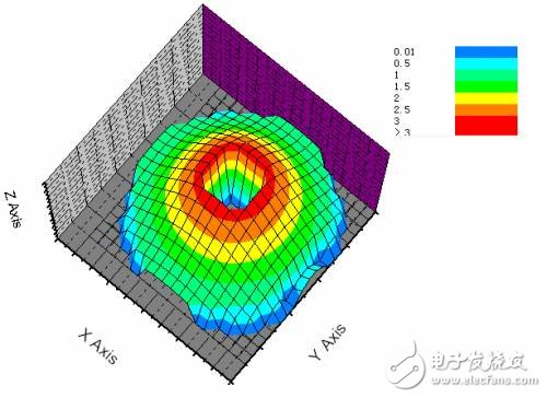
Figure 2 is a schematic diagram of the excitation distribution after removing 4*4 array elements from the center of the uniform array.
The change of the side lobes of the main surface pattern before and after the antenna array is removed in the antenna array is shown in Fig. 3.
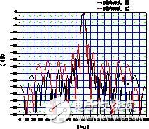
Figure 3 Main surface pattern before and after opening the center of the antenna array
It can be seen that the side lobes of the antenna are raised from the original -26dB to -19dB, because the excitation amplitude of the central region is the largest, and the weight of the antenna side lobes is sensitive. When the excitation of the central region is lost, the deterioration of the antenna side lobes is deteriorated. Based on the global optimization algorithm such as genetic algorithm (GA), a new optimization method for this non-uniform array is proposed. The circular port surface excitation distribution of the non-uniform array is shown in Fig. 4. The side lobes of the main surface of the antenna can be optimized by this method to be less than -25 dB, and the effect is very remarkable.
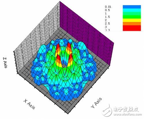
Fig. 4 The circular orifice excitation distribution of the central opening based on GA optimization
2.2 Consider the mutual coupling elimination between the slot elements according to the characteristics of the center opening
Comparing the excitation distribution of the uniform array and the non-uniform array sidelobe weighting (see Figure 1 and Figure 4), there are two distinct differences: one is that the excitation amplitude of the uniform array is the largest at the center, while the central opening is The non-uniform array excitation amplitude is zero in the central region, and the maximum excitation amplitude appears around the central region; the second is that the uniform array from the center to the antenna edge is excited from large to small, and the central aperture is non-uniform. The magnitude of the excitation is abruptly changed by the GA sidelobe weighted optimization. Therefore, when designing the slot array of the opening of the center, eliminating the mutual coupling between the array elements requires comprehensive consideration of the characteristics of the excitation distribution of the central aperture array.
The design of the slot array can be solved by Elloit's three formulas. Its design formula is as follows:

3.1 Antenna array element selection
The antenna design example uses the millimeter wave band. For the millimeter wave band, since the structural size is very small, the design parameters are required to have good design accuracy.
The specific requirements of the antenna are:
Frequency: 35GHz
The antenna has a diameter of 138 mm and a hole having a diameter of 25.4 mm is opened in the middle.
The waveguide size is selected to be 5.74 mm wide and 2.8 mm narrow. The radiation waveguide is the same size as the feed waveguide. After calculation, there are 300 array elements in the array after opening. The antenna array is divided into four zones to implement a single-pulse antenna and beam and azimuth pitch difference beams.
3.2 Design of excitation amplitude of array elements
Using the GA optimization design, the circular port surface excitation distribution is shown in Fig. 4. The excitation amplitude distribution on the main surface is shown in Fig. 5.
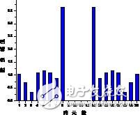
Fig.5 Distribution of excitation amplitude on the main surface of the center opening aperture after weighting
3.3 Antenna design result simulation
According to the excitation distribution of the antenna, the electrical dimensions of the central aperture non-uniform slot array weighted by the sidelobe are obtained by Elloit's formula design. The model is built in the electromagnetic field simulation software for simulation analysis. The simulation model is shown in Figure 6. The simulation results of the pattern are shown in Figures 7 to 9, respectively.
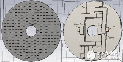
Figure 6 Simulation model of the antenna (front and back)
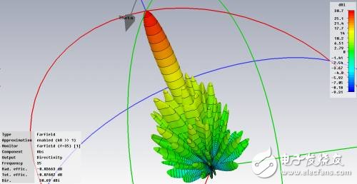
Figure 7 Stereoscopic view of the antenna (and beam)
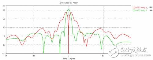
Figure 8 Antenna E and the difference pattern
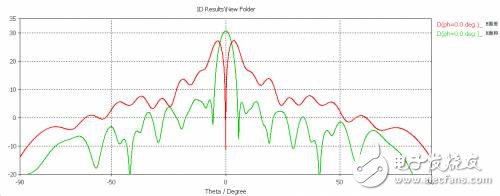
Figure 9 Antenna H plane and difference pattern
As a result of the simulation, the gain of the antenna can reach 30.75 dB without considering the loss of the feeder. The E-plane of the antenna has a beamwidth of 4.6° and the sidelobe level of the antenna is no more than -24.9 dB. The sum of the H-plane of the antenna and the beam width is 4.3°, and the sidelobe level of the antenna is not more than -24.5 dB.
4 ConclusionThrough the research and design of this novel centrally-opened single-pulse slot array antenna, the antenna design result with excellent performance is obtained, which can be used in the composite seeker design, and is very useful for the new generation of composite seeker applications. Important practical significance.
Rod core coil is winding the copper wire onto a Mn-zn or Ni-Zn Ferrite Core. Their features are high current capacity, low core loss at frequency and high magnetic saturation. Customized designs available for different request Applications. They usually be used in Switching regulators, Motors, Power amplifiers, Power supplies, Broadband filtering, Typical in VHF.

| Mode: | Air inductor ferrite rod antenna used for radio antenna, LF/HF RFID antenna/Rod core induction coil |
| Material: | NiZn,MnZn, soft ferrite rod core. |
| Application |
Led light driver, GPS,Computer,Audio/video components, Electric PCB board,switch,various current circuits,filters,AC adapter,air conditioning,Car Ignitor,...ETC |
| Inductance: | 1uH-1H |
| IDC: | 0.1A-30A |
| Certificated: |
ISO9001-2015, SGS-ROHS. |
| MOQ: | No MOQ for the trial order. |
| Samples/Delivery: | 1-5pcs free samples for freight collect. /5-10days. |
| Type of payment: | T/T, Western Union, L/C, Alipay,Paypal,etc. D/A/... |
| Features: | Inductors,high current RF transformer made with soft ferrite core, include NiZn, MnZn, Amorphous, Iron powder metal core for winding, tinned, guled,content toroidal inductor, rod inductor, drum inductor,smd chip inductor coil,widely used in many PCB boards, for filers, EMI/EMC, Anti-noise,Amplifier,RF transformer,..... |
| Advantage: |
1.Ferrite core and inductor Factory. 2.Good quality products with factory price. 3.Enough production capacity provide good delivery time. 4.Special products customized accepted. 5.Good aftersales services. |


Rod Core Coil,R Bar Coil,Rod Core Choke,Magnetic Rod Inductor
Shaanxi Magason-tech Electronics Co.,Ltd , https://www.magason-tech.com