
With the development of electronic technology, multi-frequency operation is becoming more and more popular in radar, microwave, communication and other application systems, and the requirements for the separation frequency are correspondingly increased, and a large number of high-performance filters are required. Therefore, filters have a wide range of applications in microwave and millimeter wave circuits. In the low frequency band application, the lumped parameter filter has a good performance, but as the frequency rises above the microwave frequency band, the Q value of the lumped parameter components (capacitance, inductance) drops sharply, causing the insertion loss of the filter too. Large, then it is necessary to replace the lumped parameter elements with distributed parameter elements, but the size of the distributed parameter element filters is generally large, so it is necessary to reduce the size of the microwave millimeter wave circuit filter.
In 2000, Professor Xue Quan of the City University of Hong Kong proposed a compact microstrip resonator (CMRC), after which a spiral compact microstrip resonator (SCMRC) and a linear compact microstrip resonator (BCMRC) were successively proposed. However, the SCMRC structure has a small stopband range (5.2 GHz-7.6 GHz), and BCMRC usually requires several cells to achieve better low-pass characteristics due to the unsatisfactory attenuation characteristics in the stopband range. In response to these problems, this paper proposes a new CMRC wideband low-pass filter with a maximum insertion loss of 0.3dB in the low-pass frequency range of 0-7GHz and a stopband frequency range of 8.5GHz-22.1GHz below -10dB. Below -20dB, the stopband frequency range is 9GHz-20.8GHz. It can be seen that the filter has low insertion loss in the passband and good attenuation characteristics in the stopband.
2, structure and equivalent circuitThe new CMRC planar structure proposed in this paper is shown in Figure 1, and its LC equivalent circuit model is shown in Figure 2. The dielectric substrate is Taconic CER_10, which has a dielectric constant er=9.5 and a thickness of 0.64 mm.
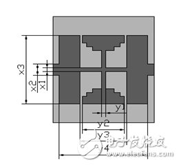
Figure 1. Planar structure of CMRC
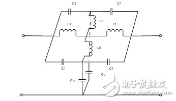
Figure 2. LC equivalent circuit model
3. Simulation analysis of filter characteristics3.1. Influence of main structural parameters on transmission characteristics
We modeled and simulated the HFSS applied to the CMRC structure shown in Figure 1, and analyzed the effects of the main structural parameters on the transmission characteristics of the filter. In the simulation, we find that x1, y1 and y2 have a great influence on the transmission characteristics of the filter. The influence characteristic curve is shown in Fig. 3 to Fig. 5. It can be seen from Fig. 3 and Fig. 4 that reducing the x1 and y1 can reduce the resonance frequency. Accordingly, the low-pass frequency range can be reduced accordingly, because in the equivalent circuit model, reducing the x1 or y1 can increase the distributed series inductance (L0 and L1) per unit length. The resonant frequency, it can be seen that the increase of L0 and L1 will correspondingly reduce the resonant frequency.
Figure 5 shows the effect of the y2 size on the transmission coefficient. The closer the value of y2 is to y3, the lower the resonance frequency. This is because increasing the y2 can increase the capacitance per unit length of the microstrip portion. In addition, the reduction of the gap increases the edge coupling capacitance, which leads to an increase in the equivalent capacitance C1, thereby reducing the resonance frequency and reducing the low frequency. Through frequency range.
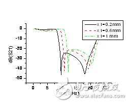
Figure 3. Transmission coefficient variation with structural parameter x1
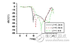
Figure 4. Variation of transmission coefficient with structural parameter y1
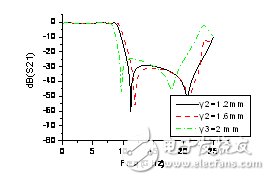
Figure 5. Transmission coefficient variation with structural parameter y2
3.2. Optimization results and their main parameters
After the above analysis, the CMRC broadband low-pass filter is optimized, and a good output S-parameter characteristic curve is obtained as shown in Fig. 6. The maximum insertion loss in the low-pass frequency range of 0 to 7 GHz is 0.3 dB, which is lower than - The 10dB stopband frequency range is 8.5GHz-22.1GHz, and the stopband frequency range below -20dB is 9GHz-20.8GHz. It can be seen that the broadband low-pass filter has good low-pass and stop-band attenuation characteristics. The main microstrip distribution parameters at this time are given in Table 1.
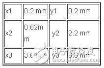
Table 1, main microstrip structure parameters
4, the conclusionThe filter has low insertion loss in the wide passband range and excellent attenuation characteristics in the wide stopband range. It can be used in the IF filter of high IF mixers and can effectively suppress the local oscillator and its harmonics. Wave component. In addition, the broadband low-pass filter is small in size and has the advantage of being easy to integrate.
Linear Array Sensor,Infrared Light Detector Device,Swir Linear Detector,Infrared Ingaas Sensor
Ningbo NaXin Perception Intelligent Technology CO., Ltd. , https://www.nicswir.com