Hello, everyone, and it's time for daily learning. In the previous post entitled "Recommended: FPGA-based CRC generator", it was mentioned that "To achieve this, we still need the LFSR circuit." "Introduction to the Circuit Characteristics in the Pseudo-Random Number of LFSR", in this supplementary article, "The FPGA Generates a Pseudo-Random Number Based on LFSR", welcomes everyone to exchange ideas.
1. Concept A certain set of artificially generated periodic sequences can be obtained by performing certain operations on a previously selected random seed. In this set of sequences, one of the numbers is selected with the same probability. The number is called pseudo Random numbers, because the selected numbers are not completely random, but from a practical point of view, the degree of randomness is sufficient. The meaning of “pseudo†here is that since the random number is generated according to a certain algorithm simulation, the result is determined and is visible, and therefore it is not a true random number. The selection of pseudo-random numbers starts with random seeds, so in order to ensure that each time the obtained pseudo-random number is sufficiently "random", the selection of random seeds is very important. If random seeds are used, then the same random number generator is used. The resulting random number will also be the same.
2. Generation method derived from LFSR The most common way to generate pseudo-random numbers is to use a linear feedback shift register (LFSR), which consists of n D flip-flops and XOR gates, as shown in the following figure: 
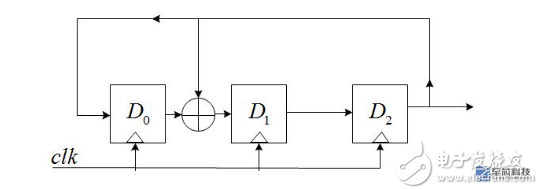
Among them, gn is the feedback coefficient, and the value can only be 0 or 1. When it is 0, it means there is no such feedback path. When it is 1, it means that there is such a feedback path; n D flip-flops can provide up to 2^n -1 states (does not include all 0 states), in order to ensure that these states are not repeated, the choice of gn must meet certain conditions. The following uses n=3, g0=1, g1=1, g2=0, and g3=1 as examples to illustrate the characteristics of the LFSR. The following figure shows the LFSR structure with this parameter: 
Assuming D2D1D0=111(seed) at the beginning, then when the clock arrives, there are:
D2=D1_OUT=1;
D1=D0_OUT^D2_OUT=0;
D0=D2_OUT=1;
That is, D2D1D0 = 101; Similarly, when another clock arrives, D2D1D0 = 001.
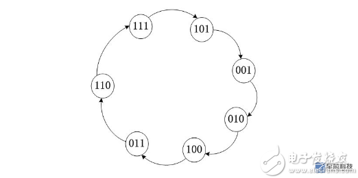
Draw the state transition diagram as follows: 
As can be seen from the figure, there are exactly 2^3-1 = 7 states, not including all 0;
If you understand the above picture, you can get at least three conclusions:
1) The initial state is provided by SEED;
2) When the feedback coefficients are different, the resulting state transition diagram is also different; it must be ensured that gn == =1, where else is the feedback?
3) The more the number of D flip-flops, the more states they produce, and the more "random" they are;
3.verilog implementation
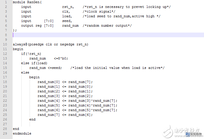
Based on the above principle, the following uses verilog to generate a pseudo-random number generator with n=8 and a feedback coefficient of g0g1g2g3g4g5g6g7g8=101110001, which has a total of 2^8=255 states. The structure of the LFSR is as follows: 
The verilog source code is as follows: 
Simulation waveform: 
With 1111 1111 as the seed, after the load signal is asserted, it begins to cycle through the 255 states, and the output values ​​255, 143, 111, ... can be used as pseudo-random numbers.
This supplement comes here, everyone, come on.
Dry Type Power Transformer,Dry Distribution Transformer,Cast Resin Transformer,Dry Type Electrical Transformer
SANON DOTRANSÂ Co., Ltd. , https://www.sntctransformer.com
