
With the continuous advancement of semiconductor technology (according to Moore's Law), there are more and more logic function peripherals integrated in the MCU, and the memory is also increasing. Consumers are increasingly demanding more energy-efficient (economic and regulatory emissions requirements), comfort, connectivity, safety (functional safety and information security) requirements, especially in recent years, new energy electric vehicles, car networking and The rise of automatic driving technology has greatly accelerated the development of automotive electronics technology. The integrated functions of the automotive electronic control unit (ECU) have become increasingly complex. In response to software remote (online) functional upgrades (adding new features) and bug fixes, the need for a bootloader (boot loader) has increased. The more you come. This article describes in detail the general working principle and development points of the automotive electronic ECU bootloader, which is applicable to the development of all automotive electronic ECU bootloaders.

The BootLoader, as the name implies, is a program loading code that resides in the ECU non-volatile memory. After each ECU reset, the bootloader runs. It will check if there is a remote program load request from the communication bus, and if so, enter the bootloader mode, establish the bus communication with the program download side (usually a PC host) and receive the application downloaded by the communication bus, resolve its address and Data code, run the NVM (None Valitale Momory) driver, program it into NVM, and verify its integrity to complete the application update. If there is no remote program load request from the communication bus, then jump directly to the application reset entry function (Reset Interrupt ISR, also known as Entry_Point() - Using the Code Expert of Processor Expert or Startup() function - Generic CodeWarrior project ), run the application.
Based on this, the three main concepts of the bootloader of the automotive ECU are as follows:
Establish reliable bus communication with the remote program downloader to obtain applications to be updated;
Parse the application programming file (S19/HEX/BIN) to obtain its address and program code and data in NVM;
Run the NVM driver to program the application code and data into NVM and verify it;
Second, how to establish a reliable bus communication?The common data bus of the car ECU is CAN and LIN, so usually the bootloader of the car ECU downloads the data through CAN or LIN. Of course, it can also be based on other buses, for example based on SPI bus or I2C bus (typically like some functional safety ECUs with safety monitoring, through the main MCU to upgrade the program of the functional safety monitoring MCU) and Ethernet (Central control based on Enternet communication) Or the full LCD meter ECU and the next-generation high-speed gateway and ADAS ECU).
TIps:
a. Different ECU communication buses are not the same. The specific need to use a certain kind of communication bus depends on the actual application;
b. The communication bus is implemented by the MCU's MCU peripherals. Therefore, the corresponding communication bus peripheral driver must be developed in the bootloader to realize the basic data sending and receiving functions.
c. In order to ensure the reliability of communication, a communication protocol based on a communication bus must be developed. A request command, an acknowledgement, a block wait, and an error must be established between the application downloader and the bootloader. Error re-send and other mechanisms ---- the bootloader completes different tasks according to different request commands and confirms whether the operation is completed (ACK) and whether the data is being transmitted completely. If there is data error (pass the checksum Or ECC), automatic retransmission is required;
d. The application downloader needs to develop GUI software based on VC or C#, QT, Labview, etc. on the PC to implement the bus communication protocol required in c. Generally, the bottom layer of the application downloads the corresponding bus device, such as USB to CAN. The interface of the dynamic library (DLL) of the /LIN transponder device implements data transmission and reception, and the corresponding bus USB forwarding device will provide a corresponding driver library (DLL). Therefore, bootloader developers generally need to have certain PC software development capabilities;
e. In order to achieve reliable transmission of data, the source code is generally added in the bus communication protocol. That is, valid data is checked or ECC calculated in the transmission and the result is sent together with valid data in the communication data frame. The bootloader receives the result. The end, after receiving the data frame, performs the same checksum or ECC calculation on the sending end of the valid data field, and compares the result with the received checksum or ECC calculation result value to judge the integrity of the data. The application programming file (S19/HEX/BIN) has a corresponding checksum mechanism, so it can take the form of directly transferring the program programming file line; otherwise, the user needs to first analyze the programming file in the upper computer software, and then the Addresses and data and code packages are packaged into some kind of customized communication protocol, and they have to be unpacked in the bootloader. This is a bit troublesome, but some OEMs have their own for intellectual property protection. The bootloader protocol, in this case, the bootloader developer must be developed in accordance with the requirements of the host plant;
f. Some formal major OEMs require their ECU suppliers to develop ECU bootloaders must be based on bus diagnostic protocols such as UDS. UDS specifies the corresponding CAN IDs for use with bootloaders. So the bootloader projects in such ECUs must be performed for a long time. Join the corresponding UDS protocol stack;

Different MCU software development IDE compilation links generated by the programming file format may be different, but the S19, HEX and BIN files can be converted to each other, so only need to open a program file in the bootloader resolver on it, other Can use the corresponding conversion tool (convert tool) to convert on the host computer;
The purpose of parsing the programming file is to obtain the program code and data of the application and its storage address in the NVM;
In order to parse the programming file, you must first understand the encoding format and the principle. For the commonly used S19, HEX, and BIN file formats, refer to the following Wikipedia links:
S19 file: https://en.wikipedia.org/wiki/SREC_(file_format)
HEX file: https://en.wikipedia.org/wiki/Intel_HEX
BIN file: https://en.wikipedia.org/wiki/Binary_file
TIps:
Both S19 and HEX files can be opened directly using a text editor (such as Notepad, Notepad++). Simply merge the S19 file lines containing the address and data codes S1, S2, and S3, and you can manually copy them. Can write window batch script to deal with; of course, there are also special to support the merger of the two S19 files, the Internet can find a lot of open source software, such as the common Srecord;
MCU's software development IDE generally integrates conversion tools between different programming files: for example, S32DS's objcopy (Create Flash Image)
And Keil's Motorola S-Record to BINARY File Converter http://
Fourth, NVM driver developmentThe NVM of the ECU generally includes EEPROM or Data-Flash integrated in its MCU chip for storing data, Code-Flash/Program-Flash for storing program code/data, and off-chip NOR Flash or NAND-Flash extended by MPU; The NVM driver includes basic operations such as erase, program, and verify for NVM, as well as NVM encryption/unsecure protection and protecTIon/deprotection. (unprotecTIon) operation.
Tips:
a, MCU on-chip integrated NVM EEPROM / D-Flash and C_Flash / P-Flash generally belong to different blocks, so you can run NVM directly on the Flash EEPROM / D-Flash erase and programming operations;
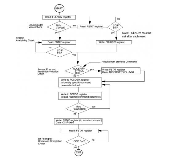
b. The NVM driver generally completes by running an NVM command sequence, in which different NVM operation command codes, NVM programming data, and target addresses are given by the NVM controller registers. A typical NVM command sequence is as follows (Freescale S12) (X) series MCU Flash write command sequence):
c. Since the operating speed of the NVM is generally lower than the CPU core frequency and the bus frequency, the NVM must be initialized before the NVM driver is run, and the operating frequency of the frequency divider is set to the frequency range required for normal operation.
d, MCU on-chip NVM can not run the NVM drive on the same block to erase and program itself, otherwise it will read the bus access violation read while write (Each NVM block only one data bus, a time only Can read or write, does not support simultaneous read and write). Therefore, for an MCU that has only one block Flash, it must call its NVM driver in RAM to erase and program itself, and must disable the CPU global interrupt during the launch of the Flash command to wait for the command to complete. Peripheral interrupt response, otherwise both the interrupt vector and the running interrupt ISR will access Flash. To enable interrupts, you must offset the interrupt vector table to RAM or NVM block (EEPROM/D-Flash) and copy the interrupt ISR to another RAM or NVM block (of course the interrupt vector table must also be updated New interrupt ISR);
e, due to the requirements of b, usually need to copy the bootloader NVM driver to run in the MCU's RAM, which can be copied to the NVM to run in RAM, you can also just copy the NVM command launch to wait for command to complete a few The instruction to the RAM can be executed because other operations in the NVM driver (such as filling in NVM operation commands, writing programming addresses, and data, etc.) do not write data to the NVM on the occupied data bus;
f. The NVM driver resides in Flash. If an unexpected program such as a stack overflow runs accidentally on the NVM driver, it will cause the accidental erasure of the NVM contents to be lost or modified. Therefore, the key data or code (such as the bootloader itself) needs to be protected against accidental modification, or the safer method is not to store the NVM driver in the NVM. Instead, the bootloader first downloads it to the RAM through the host computer. In the middle run, after the bootloader is over, the area RAM is cleared to avoid NVM data loss and modification caused by accidental running of the NVM driver. (PS: Afterwards, I will write an article specifically to introduce related methods. Please pay attention to reading.)
g. General MCU vendors will provide NVM driver libraries for their MCUs. Users can use this library to implement NVM operations. If they are Freescale/NXP automotive MCUs, they can also use CodeWarrior IDE integrated Processor Expert to generate corresponding NVM drivers. ;
Fifth, bootloader development of other pointsa, bootloader and application relationship
Bootloader and application are two complete MCU software projects, each with its own startup code, main() function, link file, peripheral driver, and interrupt vector table;
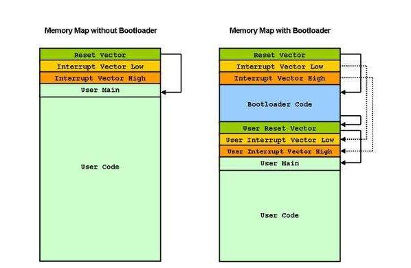
Therefore, in the link file of the bootloader and the application, the allocation of the address space to the NVM must be separated and can not be overlapped, but its RAM allocation is not constrained. Both can use the entire RAM space, because after jump to the application project, The startup code will reinitialize the RAM;
The bootloader must use the MCU's default interrupt vector table, because after each reset the MCU takes its address from the reset vector of its default interrupt vector table; the application's interrupt vector must be offset (via the corresponding interrupt vector offset register , such as IVBR register of S12 (X) series MCU or SCB-Vtor register of ARM Cortex M series MCU; and NVM (P-Flash) erase is performed according to sector, so in order to make full use of NVM (P- In the Flash (Flash) space, the bootloader is partitioned into several NVM (P-Flash) sectors containing the default interrupt vector table (SVM (S12 (X) series MCU NVM last sector, ARM Cortex M series MCU starting from 0 address sectors);
Tips:
If the new process of the application is interrupted or reset unexpectedly, the application update fails, and the corresponding application program integrity cannot be verified. Of course, the application must be downloaded again. In order to avoid the loss of the application in this case, the BootLoader often needs to apply to the application. Perform a dual backup, that is, use two different NVM partitions to save the application. Only after the new application is updated successfully, do you erase the old application. Otherwise, you will run the old application after the next reset.
b, jump from bootloader to application
After developing and using the bootloader, the bootloader will be run first after each ECU reset. If there is no remote application download request, it will directly jump to the application reset function address. There are two problems to be considered:
How to get the application reset function address: The methods are: 1) fix the application's reset start function address through the link file; 2) obtain the reset vector address from the application's interrupt vector table; recommended method 2): because of its good flexibility, Every time the application changes, you don't need to care about the application reset function being compiled to the specific address of the NVM. You only need to remove the reset vector from the application's interrupt vector table:
The typical method is as follows (assuming the application interrupt vector table base address register IVBR=0x7F of the S12(X) series MCU):
Typedef void (*near tIsrFunc)(void);/* ISR prototype definition */
Word *Ptr; /*pointer used for ISR vector fecth*/
Ptr = (word *)0x7FFE; /*get the ISR vector from the interrupt vector table of APP project */
((tIsrFunc)(*Ptr))(); /*covert and run*/
Jump timing: Methods are as follows: 1) After the bootloader has updated the application and verified its integrity, OK, the used peripherals (such as CAN/LIN communication bus module, timer, GPIO, etc.) registers are restored to after reset. The default state, and then jump directly; bootloader update the application and check the integrity of the OK, wait for the watchdog timer timeout overflow reset, at the beginning of the bootloader to determine no remote application download request and jump; recommended method 2): Because the method 1) is relative to the software reset, it may have a difference between the MCU's hardware environment and the direct-running application program when jumping to the application reset start function, and the watchdog reset of the method 2) belongs to the hardware reset. Most of the peripheral (analog, clock, and peripheral) circuitry will be reset and will be closer to running the application directly.
c, the development of bootloader need to master the knowledge and debugging techniques
First, the development of the bootloader requires that the MCU's RAM and NVM resources used by the ECU are clear and then partitioned to ensure that there is no overlap between the NVM allocation of the application and the bootloader. Therefore, it is necessary to understand how to use the link file of the software development tool IDE and how to write it.
Then, we need to judge whether the interrupt vector table offset is successful, NVM driver copy the address and size, and other information, so we must master the software development tool IDE compiler link results in the map file specific information;
In addition, it is also useful to know how to redirect NVM functions (separate memory address and runtime address of function program code) into RAM.
Tips:
When developing an application program, it needs to be separately debugged to ensure its normal function. At this time, although its peripheral interrupt vector table has been offset, its reset vector must be placed in the default interrupt vector table where the reset vector is located. Address, otherwise it will not work after download, normal debugging, because if the application's reset vector is placed in the offset application vector vector table, the default reset vector content is 0xFFFF (Flash erased state) The CPU core will run to the address fetch of 0xFFFF. It is obviously not a real project start function, so it cannot be run. The result is the same as the case where a new MCU is not written to any program and it will continue to appear illegal. Reset; and after the application development is completed, it is offset to the application interrupt vector to avoid the flash address conflict with the bootloader project;
Finally, it is also very practical to master the debug information in the elf file by using the Hotsync or attach method of the debugger to debug the bootloader and the application program seamlessly, which can greatly improve the debugging efficiency of the bootloader.
d, download method of bootloader and application during mass production
It is recommended to merge the program files generated by the bootloader and the application program and link them, and then use a mass production tool (such as the Cyclone programmer) to download them at a time to increase the production efficiency.
wired backlight gaming keyboard
Gaming keyboard with laser curving keypad, led backlit, blue , red, green colors are available,suspension button design, perfect Mechanical hand feeling !
Gaming Keyboard,Wired Rgb Game Keyboard,Wire Smart Keyboard,Game Controller
MICROBITS TECHNOLOGY LIMITED , https://www.hkmicrobits.com