
Software Radio, Software Defined Radio, SDR. In general terms, SDR is based on a common hardware platform to implement various communication modules using software.
There are two key words in the concept, "Universal Hardware Platform" and "Software." "Universal hardware platform" means that we can implement a variety of communication functions based on this hardware platform, rather than saying that a hardware platform can only implement one communication function. The "software" to implement the communication module is relative to the traditional radio technology. The traditional radio communication module is designed with hardware circuits. A communication circuit can only complete one communication function, with long development cycle and high development cost. And once the design is done, the function cannot be changed. Softwareization can speed up the development of communication modules, reduce development costs, and facilitate debugging and maintenance.
We can use Figure 1 to briefly see the difference between a software radio base station and a traditional radio base station. On the left side of the picture is a traditional large base station, and on the right side of the picture is a miniaturized base station based on software radio. Traditional commercial base stations are large in size, and many dedicated hardware circuits need to be designed. The SDR base station is small in size, and most of the communication functions are implemented by software.
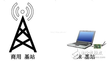
Figure 1 Commercial base station and SDR base station
SDR technology is hailed as the third revolution in communications. The first revolution was a 1G communication system, a revolution from wired communication to wireless communication; the second revolution was a 2G communication system, a revolution from analog communication to digital communication. SDR is the development trend of future communication systems.
Principle of SDR systemThe following begins to explain the system principle of SDR. In the above introduction we know that GPP-Based SDR systems generally contain a GPP and a peripheral. Let's take a laptop to connect a USRP B200 as an example to explain the internal implementation of the SDR system.
.1 transmitter
First, let's look at the system schematic of the transmitter, Figure 7. The left side of the figure is a schematic diagram of a notebook, and the right side of a USRP B200 is a schematic diagram of the launch.
First look at the top SDR program in the notebook structure. This program is the communication module we use software to implement. In the notebook, we can use various high-level programming languages ​​to write various communication modules, such as Turbo coding module, OFDM module and so on. In view of the high real-time requirements of SDR systems, we generally use C or C++ language to write SDR programs. The SDR program contains the complete protocol stack of the communication system. If we write the LTE system, it includes PHY, MAC, RLC, PDCP, RRC, NAS, and even MME. If we are a WiFi system, it includes PHY and MAC. , LLC, etc. The main function of the SDR program is to process the baseband data of the system.
Next, UHD is the driver module of the USRP device. Different peripherals use different drivers. Because we use USRPB200 as an example, the driver module is UHD. For the installation method of the UHD driver, see the UHD library function called in C or C++.
Next is the system's various system libraries and interfaces to the system calls and the kernel. To emphasize that most SDR programs are developed based on Linux and rarely based on Windows development. Because the Linux system is open source and has good real-time performance. This piece is mainly about operating system knowledge, we will not discuss it in depth here.
The interface between USRP B200 and GPP is USB3.0. The choice of peripheral interface is also very important. The transmission rate of the interface must be fast and cannot become the bottleneck of the entire system. The early USRP products used USB2.0 interfaces, because the communication system's throughput was small, so it was not restricted. Most peripherals now use USB 3.0 or Ethernet network ports as peripheral interfaces. The interface speed of USB3.0 can reach 500MBps, which can basically meet the needs of most communication systems.
The laptop then transmits the data to the USRP B200 via USB 3.0. The two modules at the bottom of the USRP are the transmit control module and the digital up-conversion module (DUC). These two modules are implemented in the FPGA. The advantage of using FPGA is that the processing speed is fast. The transmission control module is well understood to control the sending behavior of the entire USRP, such as when to send. The DUC module is used to upconvert the baseband data generated by the computer to the intermediate frequency. After that, the digital signal is converted into analog domain data after passing through the USRP DAC. After the digital-to-analog conversion, a low-pass filter is needed to make the signal smoother. The final IF analog domain data is that the signal multiplied by the crystal oscillator modulates our IF signal to the defined RF frequency.
Finally, the RF signal is transmitted through the power amplifier. There is also a lot of knowledge in the signal amplifier to learn. For example, signal amplifiers are classified into Class A, Class B, and Class C. The characteristics of each class are not specifically explained in this paper. We can modify the transmit gain of the transmitted signal, ie tx_gain, through the library function provided by UHD. The tx_gain parameter has a large effect on the signal. If the tx_gain setting is too small, the signal power is too small. If the setting is too large, the system may cause low noise rise, which may affect the normal operation of other communication systems.
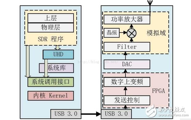
Figure 2 SDR transmitter schematic
2 receiver
Some people may ask why they have to go through two conversions. We will explain it to you with the SDR receiver. Figure 8 shows the schematic of the SDR receiver. Similarly, the left side is a schematic diagram of the notebook, the same as the transmitter; the right side is the receiving diagram of the USRP, and the USRP reception diagram is slightly different from the transmission diagram.
First, the receiving part of the amplifier becomes a low-noise amplifier. As the name suggests, low-noise amplifiers are low-noise amplifiers, essentially an amplifier. Because the received signal contains the noise of the channel, the receiver cannot put the noise too large.
After the signal is low-noise, it is multiplied by the signal generated by the USRP crystal to down-convert the signal to the intermediate frequency, and similarly through a low-pass filter to smooth the signal.
The IF signal then passes through the ADC to transfer the signal from the analog domain to the data domain. The ADC is a very important part of the USRP. The ADC is mainly composed of two parameters, sampling accuracy and sampling rate. The sampling accuracy indicates how many bits are used for the sampled signal. For example, the ADC accuracy of the USRP B200 is 12 bits, that is, each data after sampling is represented by 12 bits. The sampling rate is the sampling rate of the system, and the sampling rate of the USRP B200 is 61.44 MS/s. This is why most SDRLTE systems use the USRP B series as a peripheral. The sampling rate of 61.44 MS/s is just twice the maximum sampling rate of the LTE system of 30.72M.
Similarly, after the signal passes through the ADC, the digital signal is sent to the FPGA module for processing. The FPGA contains two modules, digital down conversion and receive control. Receive control is used to control the receiving process of the entire USRP system, such as when to start accepting. Digital down conversion, DDC, is used to downconvert the signal from the intermediate frequency to the baseband.
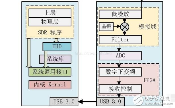
Figure 3 Schematic diagram of the SDR receiver
Why do you have to go down twice? As shown in Fig. 9, the first frequency conversion is to multiply the signal generated by the crystal oscillator in the analog domain with the radio frequency signal to down-convert the signal to the intermediate frequency. This frequency conversion is mainly for AD sampling later. We know that the sampling needs to satisfy the Nyquist sampling law. The sampling frequency must be greater than twice the highest frequency of the signal. The carrier frequency of the RF signal can reach 2.6GHz or even 5GHz, and the carrier frequency cannot be doubled. Sample rate ADC. Therefore, the system first downconverts the signal to the intermediate frequency, and then uses the ADC to perform analog-to-digital conversion on the signal. Because the sampling rate of the USRP ADC is 61.44MS/s, we can push the USRP corresponding IF frequency should be lower than 30.72MHz.
The intermediate frequency digital signal is then downconverted to baseband by the DDC. Some people may ask why not directly convert the signal to the baseband. Such a receiver is called a zero-IF receiver. If the carrier frequency is high, the design of the zero-IF receiver will be very complicated, so the zero-IF receiver is generally used in systems with lower carrier frequencies.
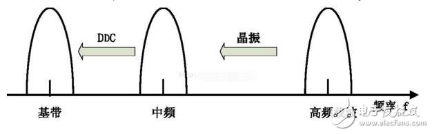
Figure 4 Schematic diagram of the down conversion principle
After the digital signal is transmitted to the laptop via the USB3.0 interface, the computer transmits the data to the SDR program for processing. After the physical layer is processed, the data is handed over to the upper layer. Thus, the signal receiving process of the SDR receiver is completed.
Each module in the SDR transmitter/receiver corresponds to a large piece of knowledge, and the ocean of knowledge is infinite. The introduction here can only play a role in attracting jade. If you want to study in depth, you have to check the information.
Diamond turning and diamond boring
Both diamond turning and diamond boring are performed with polycrystalline diamond tools.
honing
Honing is to use the oil stone (also called honing bar) inlaid on the honing head to finish the hole.
grinding
Grinding is the use of coated or pressed abrasive particles embedded in the grinding tool, through the grinding tool and workpiece in a certain pressure of the relative movement of the surface for finishing processing.
superfinishing
Ultra-finishing is the finishing of the finished surface by using fine-grained whetstone mounted on the vibrating head.
Abrasive belt grinding
Belt grinding is the grinding of workpiece surface with high-speed annular belt.
Mirror grinding
Mirror surface grinding is a grinding method to achieve the optimum surface roughness. After grinding the workpiece, the surface roughness is not more than 0.01 micron, the light is like a mirror, can be clear imaging
Precision Machining,Casting Exhaust Manifold,Stainless Stee Milling,Custom Cnc Machining Part
Tianhui Machine Co.,Ltd , https://www.thcastings.com