
CAN is the abbreviation of Controller Area Network (CAN). It was developed by German BOSCH company, which is famous for developing and producing automotive electronics products, and eventually became an international standard (ISO11898). It is one of the most widely used fieldbuses in the world. At the beginning of the establishment, the CAN bus is positioned in the field bus inside the car, which has the advantages of fast transmission speed, high reliability and flexibility. In the 1990s, CAN bus began to be gradually promoted in the automotive electronics industry. It has become the communication protocol of choice in the automotive electronics industry, and has been widely used in medical equipment, industrial production, building facilities, transportation and other fields.
Layered structure of CAN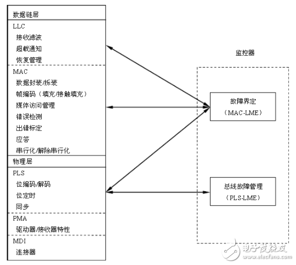
The data link layer of CAN is its core content, in which Logical Link Control (LLC) performs functions such as filtering, overload notification and management recovery, and media access control (MAC) sub-layer completes data packing/ Unpacking, frame coding, media access management, error detection, error signaling, acknowledgment, serial-to-parallel conversion, and more. These functions are all built around the information frame transfer process.
The function of the Logical Link Control Sublayer (LLC): Serving data transmission and remote data requests, confirming that messages received by the LLC sublayer have actually been received, providing information for recovery management and notification overloading. There is a lot of flexibility in defining target processing.
The function of the medium access control sublayer (MAC): mainly the transmission rules, namely control frame structure, execution arbitration, error detection, error calibration and fault definition. The MAC sublayer also determines if the bus is open or starts receiving immediately when a new transfer is initiated. The bit timing feature is also part of the MAC sublayer.
Frame typeThere are two different frame formats in the CAN2.0B version protocol, the difference being that the length of the identifier field is different, the frame containing the 11-bit identifier is called a standard frame, and the frame containing the 29-bit identifier is called Extended frame. As described in the CAN 1.2 version protocol, the two versions of the standard data frame format and the remote frame format are equivalent, respectively, and the extended format is a newly added feature of the CAN 2.0B protocol. In order to make the controller design relatively simple, it is not required to implement a full extended format. For the new controller, the standard format must be supported without any restrictions. But no matter which frame format, there are four different types of frames in the message transmission.
When a message is transmitted, different frames have different transmission structures. The structure of the four transmission frames will be separately introduced below. Only the frame transmission according to the structure can be correctly received and transmitted by the node.
(1) Data frame
It consists of seven different Bit Fields: Start of, ArbitraTIon Field, Control Field, DataField, CRC Field, and Response Domain. (ACK Field) and End of Frame. The length of the data field can be 0 to 8 bytes.
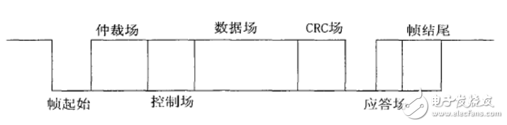
1) Start of Frame (SOF): Start of Frame (SOF) marks the beginning of a data frame and a remote frame, consisting of only one "dominant" bit. In the CAN synchronization rule, the station is allowed to start transmitting (signal) when the bus is idle (in a recessive state). All sites must be synchronized to the frame start leading edge of the site where the message is first sent (this mode is called "hard synchronization").
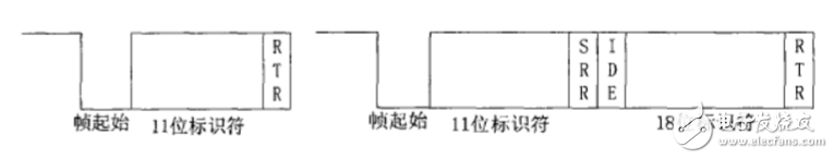
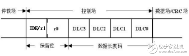
2) Arbitration domain: The arbitration domain consists of an identifier and an RTR bit. The standard frame format is different from the arbitration domain format of the extended frame format. In the standard format, the arbitration field consists of a 1l bit identifier and an RTR bit. The identifier bits are ID28 to IDl8. In the extended frame format, the arbitration field includes a 29-bit identifier, an SRR bit, an IDE (IdenTIfier Extension) bit, and an RTR bit. Its identifier has ID28~IDO. In order to distinguish between standard frame format and extended frame format, CANl. The reserved bit r1 of the 0-1.2 version protocol is now represented as an IDE bit. The IDE bit is dominant, indicating that the data frame is in the standard format; the IDE bit is recessive, indicating that the data frame is an extended frame format. In the extended frame, the SubsTItute Remote Request (SRR) bit is implicit. The arbitration domain transmission order is from the highest to the lowest, and the highest 7 cannot be all zero. The full name of the RTR is called "Remote Transmission Request". The RTR bit must be "dominant" in the data frame and "recessive" in the remote frame. It is a sign that distinguishes between data frames and remote frames.
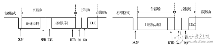
3) Control domain: The control domain consists of 6 bits, including 2 reserved bits (r0, r1 are the same as the CAN bus protocol extension) and a 4-bit data length code. The allowed data length is 0-8 bytes.
4) Data field: The data in the send buffer is sent according to the length code indicating length. The same is true for the received data. It can be 0 to 8 bytes, each byte contains 8 bits, and the MSB (most significant bit) is sent first.
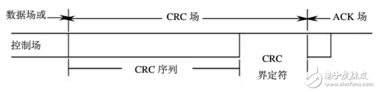
5) CRC check code field: It consists of a CRC field (15 bits) and a CRC boundary character (a recessive bit). In the CRC calculation, the divided polynomial includes the start field of the frame, the arbitration field, the control field, the data field, and the unfilled bit stream reference with 15 bits being 0. This polynomial is divided by the following polynomial X15+X14+X10+X8+X7+X4+X3+1 (the coefficient is calculated according to modulo 2), and the remainder of the division is the CRC sequence sent to the bus. When transmitting, the most significant bit of the CRC sequence is transmitted/received first. This frame check method is chosen because this CRC is optimal for frames of less than 127 bits.
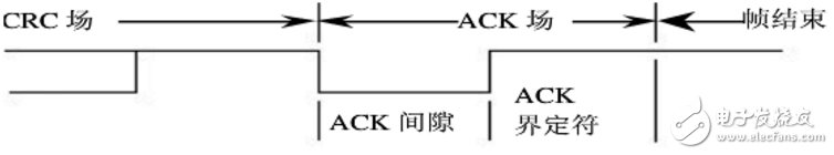
6) Response field: The response field consists of two (answer gap and response defined) recessive bits sent by the sender. All the nodes that receive the correct CRC sequence will send this recessiveness on the response gap of the sending node. The bit is rewritten as a dominant bit. Therefore, the transmitting node will always monitor the bus signal and have confirmed that at least one of the nodes in the network correctly received the transmitted information. The response delimiter is the second recessive bit in the response domain. It can be seen that there are two recessive bits on both sides of the response gap: CRC domain and response boundary location.
7) End of field: Each data frame or remote frame is terminated by a series of seven recessive bits. In this way, the receiving node can correctly detect the end of the transmission of one frame.
(2) Error frame
The error frame consists of two distinct fields: the first field is the error flag from the controller; the second field is the error delimiter.
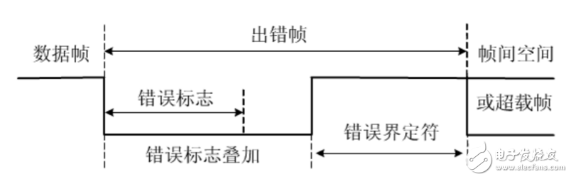
1) Error flag: There are two forms of error flags.
1 Activate (AcTIve) error flag. It consists of 6 consecutive dominant bits.
2 Passive error flag. It consists of 6 consecutive recessive bits.
It can be overwritten by the dominant bits of other CAN bus protocol controllers.
2) Error definition: The error delimiter consists of 8 recessive bits. After transmitting the error flag, each station sends a recessive bit and monitors the bus until a recessive bit is detected, and then starts sending the remaining 7 recessive bits.
(3) Remote frame
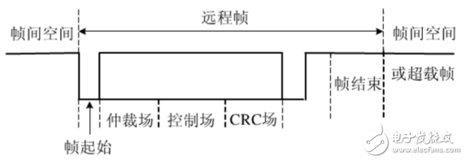
Remote frames also have standard and extended formats, and are composed of six different bit fields: frame start, arbitration field, control field, CRC field, response field, and frame end. Compared with the data frame, the RTR bit of the remote frame is recessive, there is no data field, and the data length coding field can be any value of 0-8 bytes, which is the data field length of the data frame sent by the remote frame request. When a data frame and a remote frame having the same arbitration domain are simultaneously transmitted, since the RTR bit of the data frame is dominant, the data frame is prioritized. A node that sends a remote frame can receive data directly.
(4) Overload frame
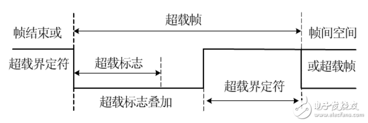
The overload frame consists of two areas: the overload identification field and the overload delimiter field. The following three states will cause an overload frame to be sent:
1) The receiver needs too much time to process the current data before receiving a frame (receiving is not ready);
2) detecting a dominant bit signal in the frame void region;
3) If the CAN node samples to a dominant bit node at the 8th bit of the error delimiter or overload delimiter, an overload frame is sent.
Full Range Woofer,Magnet Woofer,Piezo Car Tweeter,Hi-Fi Dome Tweeter
NINGBO BOILINGSOUND ELECTRONICS CO.,LTD , https://www.tweeterspeaker.com