First, the steering gear principle
The control signal enters the signal modulation chip from the channel of the receiver to obtain a DC bias voltage. It has a reference circuit inside, which generates a reference signal with a period of 20ms and a width of 1.5ms, and compares the obtained DC bias voltage with the voltage of the potentiometer to obtain a voltage difference output. Finally, the positive and negative voltage output of the voltage difference to the motor drive chip determines the forward and reverse of the motor. When the motor speed is constant, the potentiometer is rotated by the cascade reduction gear, so that the voltage difference is 0, and the motor stops rotating.
The control of the steering gear generally requires a time base pulse of about 20 ms. The high level portion of the pulse is generally an angle control pulse portion in the range of 0.5 ms to 2.5 ms, with a total interval of 2 ms. Taking the 180 degree angle servo as an example, the corresponding control relationship is this:
0.5ms--------------0 degrees;
1.0ms------------45 degrees;
1.5ms------------90 degrees;
2.0ms-----------135 degrees;
2.5ms-----------180 degrees;
(1) Follow-up characteristics of the steering gear
Suppose now that the servo is stable at point A. At this time, the CPU sends a PWM signal, and the servo is turned from point A to point B at full speed. In this process, it takes a while for the servo to move to point B.
Hold time is Tw
When Tw≥△T, the steering gear can reach the target and have the remaining time;
When Tw ≤ △ T, the steering gear cannot reach the target;
Theoretically: when Tw = â–³ T, the system is the most consistent, and the steering gear is the fastest.
In the actual process, w is not the same, and the limit ΔT during continuous motion is difficult to calculate.
When the PWM signal is sequentially changed with a minimum amount of change (1DIV=8us), the resolution of the servo is the highest, but the speed is slowed down.
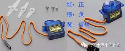
Second, the servo signal PWM signal introduction
1. Definition of PWM Signal The PWM signal is a pulse width modulated signal characterized by the time width between its rising and falling edges. The specific time-width protocol is described below. The steering gear we currently use relies mainly on the standard protocol of the model industry. With the gradual independence of the robot industry, some manufacturers have introduced new steering gear protocols. These servos can only be used in the robot industry and cannot be applied to traditional ones. The model is above. At present, the steering gear may be the product of this transition period. It adopts the traditional PWM protocol, and its advantages and disadvantages are clear at a glance. The advantage is that it has been industrialized, the cost is low, and the rotation angle is large (the current production can reach 185 degrees); The disadvantage is that the control is more complicated, after all, the PWM format is adopted. However, it is a digital servo, which has low requirements for PWM signals: (1) It does not need to receive commands at any time to reduce CPU fatigue; (2) It can be position-locked and position-tracked. Stepper motor

There are several points to note in the PWM format: (1) The rising edge is at least 0.5mS, which is between 0.5mS and 2.5mS; (2) The HG14-M digital servo has no requirement for the falling edge time. Currently, 0.5Ms is used. That is to say, the PWM waveform can be a standard square wave with a period of 1mS; (3) HG0680 is a plastic gear analog steering gear that requires continuous supply of PWM signals; it can also input a standard square wave with a period of 1mS. The following performance is very good and very close.
2. PWM signal control accuracy formulation
If the 8-bit microcontroller AT89C52CPU is used and its data resolution is 256, then it should be divided into 250 copies after the servo parameter limit experiment. Then the width of 0.5mS---2.5Ms is 2mS = 2000uS. 2000uS÷250=8uS, then: PWM control accuracy is 8us. We can control the rotation and positioning of the steering gear in increments of 8uS. The steering gear can be rotated 185 degrees, then 185 degrees ÷ 250 = 0.74 degrees, then: the steering gear control accuracy is 0.74 degrees.
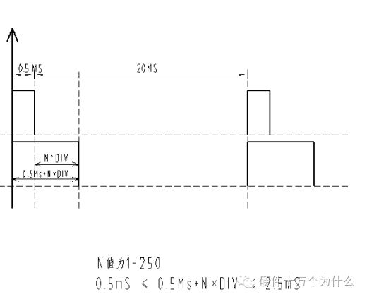
1 DIV = 8us ; The value in the 250DIV=2ms time base register is: (#01H)01 ----(#0FAH)250. A total of 185 degrees, divided into 250 locations, each location is called 1DIV. Then: 185 ÷ 250 = 0.74 degrees / DIV PWM rising edge function: 0.5ms + N × DIV 0us ≤ N × DIV ≤ 2ms 0.5ms ≤ 0.5ms + N × DIV ≤ 2.5ms
two. Single steering gear drag and speed control algorithm
1. The steering gear is the follower mechanism (1), when it is not turned to the target position, it will rotate to the target position at full speed. (2) When it reaches the target position, it will automatically remain in that position. So for digital servos, the PWM signal provides the target position, and the tracking motion depends on the steering gear itself. (3) The analog servo such as the HG0680 needs to supply the PWM signal at all times, and the servo cannot lock the target position by itself. So our control system is a target planning system. (1) Position control method of HG14-M servo The steering angle of the servo is 185 degrees. Since 8 is used for CPU control, the control precision is up to 256 copies. At present, after actual testing and planning, there are 250 copies. Divide 0-185° into 250 parts, 0.74 degrees each. The PWM width required for control is 0.5ms to 2.5ms and the width is 2ms. 2ms ÷ 250 = 8us; so it is: PWM signal = 1 degree / 8us;

(2) Movement protocol of the steering gear
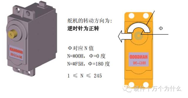
When moving, it can be connected with a large rotating load. The output torque of the steering gear is large, and the anti-jitter is very good. The linearity of the potentiometer is high, and it will not deviate from the target when it reaches the limit position.
2. Characteristics of the target planning system
(1) Follow-up characteristics of the steering gear
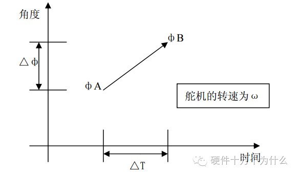
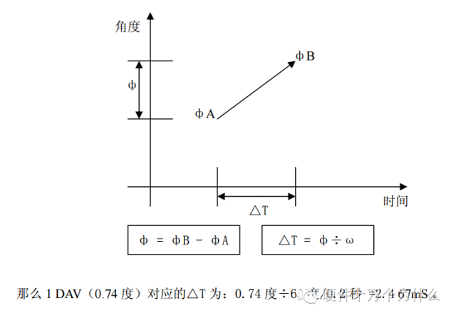
1 The servo is stable at point A; 2 The CPU sends a PWM signal with the coordinates of point B; 3 The full speed of the servo is shifted from point A to point B; △ф = фB - фA △T = △ф÷ω 4 CPU sends B point After the PWM signal, it should wait for a while, and the servo can be used to turn to point B. Then, how to calculate the specific hold (waiting) time, as follows: Let: Hold time is Tw When Tw≥△T, the servo can reach the target and have the remaining time; when Tw≤△T, the servo can't Arriving at the target; Theoretically: When Tw = △ T, the system is the most consistent, and the steering gear is the fastest. In the actual process, there are two factors: 1 1 robot has multiple steering gears, and the load is different, so ω is different; 2 the external environment load of a certain steering gear is different at different times, so ω is different; then coherent motion The time limit ΔT is difficult to calculate. The current approach is to empirically select the value of ω.
(2) The ω value of the steering gear determines that the ω value of the steering gear changes at any time, so only one average value, or the point with the highest probability of occurrence, can be measured. in accordance with
1 manufacturer's experience value; 2 using HG14-M specific test; test experiment:
1 Turn on the CPU and start delay Tw; 2 When the delay Tw arrives, observe whether the servo reaches the target; use a double pendulum program to measure the relationship between Tw and △T with the oscilloscope. (3) The rudder value of the steering gear is calculated to be 0.16--0.22 sec / 60 degrees; 0.2 sec / 60 degrees >> 1.2 sec / 360 degrees >> 0.617 sec / 185 degrees ω is 360 degrees / 1.2 seconds , 2Π/1.2 seconds ω=300 degrees/second, then the 185 degree rotation time is 185 degrees ÷ 360 degrees / 1.2 seconds = 0.6167 seconds. (4) Verification by double pendulum test
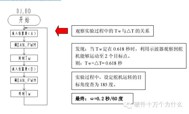
3. The definition of DAV divides the 185 degree corner into 250 average aliquots. Then: 0.74 degrees per aliquot. The definition is as follows: DAV = 0.74 degrees due to: ω = 0.2 sec / 60 degrees: the time required to run 1 DAV is: 0.72 degrees * 0.2 sec / 60 degrees = 2.4 ms;
4. The DIV defines the servo signal to support the PWM signal from 0.5ms to 2.5ms with a total interval of 2ms. If divided into 250 small parts, then 2ms ÷ 250 = 0.008 ms = 8us. The definition is as follows: DIV = 8us.
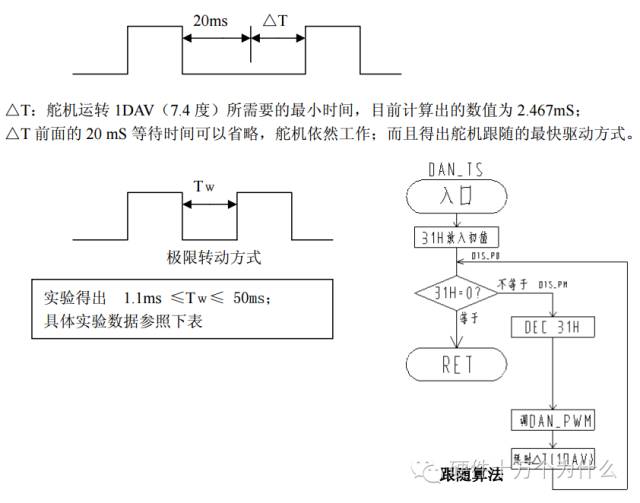
5. Single steering speed control algorithm

Test content: Pull the time of the trailing edge of the rear to 30ms. No problem, the servos work as usual.
Pulling the time of the trailing edge of the rear to 10ms is no problem, and the steering gear works as usual. Pulling the time of the trailing edge of the rear to 2.6ms is no problem, the servos work as usual. Pulling the time of the trailing edge of the rear to 500us is no problem, and the servos work as usual. Practice has shown that the falling edge time parameter can be made very small. The current experiment has dropped to 500uS and still works fine. Because:
(1) The servo circuit automatically detects the rising edge and triggers on the rising edge to monitor the PWM pulse width “headâ€. (2) The servo circuit automatically detects the falling edge and triggers on the falling edge to monitor the PWM pulse width “tailâ€.
(1) Limit falling edge PWM pulse width when the steering gear rotates
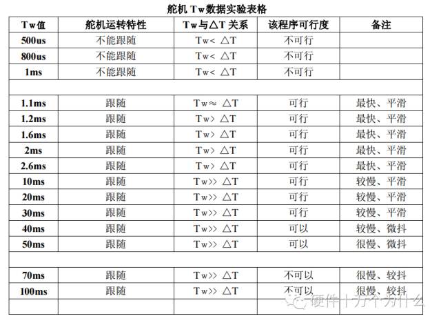
The questionable place is the performance at 1.1ms, and the Tw≈ △T is obtained; that is, 1.1ms = 2.467ms, obviously there is a problem. After considering re-observing the PWM waveform, it is found that the real starting point of the motor is as follows:
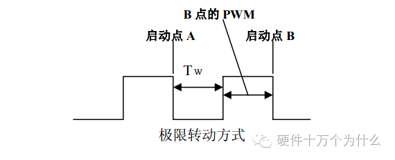
In fact, the motion time from A to B is: â–³T = Tw + (point B) PWM
16+ Years Experience Smart Watch manufacturer, ITOPNOO Provide One-stop Smart Wearable devices Solutions For You.
Our Smart Wearable products include android smart watches, Watch For iPhone, Bracelet and Wristband etc.
Leading healthcare navigation services for individuals and families who are generally healthy or face serious medical issues, and health services for employers.
The Trends New Watches Designs. Custom smart watch products designed with the vision of our clients' brands in mind.
Wholesale smart watches,Best Smart Watches,Gifts Wholesalers, smart watch manufacturer
TOPNOTCH INTERNATIONAL GROUP LIMITED , https://www.micbluetooth.com
