
With the in-depth development of the informatization construction of the launch pad, in order to realize the fully automated control of the transmitter room monitoring system, five 150kW short-wave transmitters in our computer room have newly built an automatic antenna control system. As a subsystem of the transmitter room monitoring system, the antenna control system can be controlled by the remote monitoring room to provide an antenna control interface and a data upload interface for the computer room monitoring system; it can provide manual or automatic mode, and independently complete the coaxial switch of the antenna. And the switch control of the site change switch; in the automatic state, the sky control system automatically switches the work according to the operation schedule; the antenna control operation and fault can be recorded, counted and queried; at the same time, the monitoring of the working state of the antenna and the dummy load can be completed. . The following is a brief introduction to the antenna automatic control system in my computer room.
2 The basic structure of the antenna automatic control systemThe antenna automatic control system adopts the design scheme of industrial control computer plus DI/O board with optocoupler isolation. The DI/O board with optocoupler isolation is mainly composed of several optocouplers, which can electrically isolate the antenna automatic control unit from the controlled object to ensure the stability of the system. Among them, the industrial computer uses Advantech's original IPC-610 (P42.8G, 512M, 80G hard drive, comb drive, 10/100M adaptive network card), 17-inch industrial touch screen display as the display terminal; the switch input uses Advantech PCI-1752 (64 The road enters the PC104 bus input board), and the output card adopts Advantech PCI-1754 (64-way out PC104 bus output board).
2.1 System composition
The antenna automatic control system mainly includes two parts: hardware and software.
The hardware system consists of the following three parts:
(1) Management Control Center: It is mainly composed of industrial computer and DI/O card (including peripheral devices such as touch screen, mouse, keyboard, etc.).
(2) Antenna control and state sampling unit: mainly composed of control and sampling circuits.
(3) Controlled unit: mainly composed of coaxial switch and field switch.
The software system is written in LABVIEW language, including: automatic operation, manual operation, data recording, etc.
2.2 System Control Principle
Figure 1 is a block diagram of the control principle of the antenna automatic control system. The system is managed and controlled by the industrial control computer. When controlling, the software system issues control commands to the control circuit through the DI/O card. The control circuit controls the execution unit according to the control command (controlled object: coaxial switch and site switch) The corresponding control action is performed to turn the antenna to the designated corresponding position; at the same time, the sampling circuit samples the switching state of the controlled object and feeds back to the industrial control computer through the DI/O card.

Figure 1 Antenna automatic control system control block diagram
3 hardware control section3.1 Positional relationship of controlled objects
The controlled objects of the antenna automatic control system are mainly coaxial switches and field switches, all of which are controlled by the control circuit. Figure 2 is a schematic diagram of the control of the coaxial switch (KT) and the field switch (K).
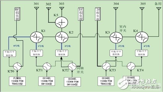
Figure 2 Schematic diagram of coaxial switch (KT) and field switch (K) control
The coaxial switch KT0-KT4 has two operating states, namely: antenna bit and dummy load bit. The antenna bit indicates that the transmitter is connected to the corresponding antenna; the dummy load bit indicates that the transmitter is connected to the corresponding dummy load. The site switches K1, K2, K3, K4, and K5 also have two working states, namely: straight through and steering. The straight through indicates that the site switch directly turns on the antenna according to the cross; the steering indicates that the site switch turns on the antenna according to the steering direction. The DJ can use any pair of antennas. C01, C02, CO3, and C04 can only use the next antenna in addition to the local antenna, that is, the C01 can be connected to 301 and 302. 303, 304, 305, spare antenna; C02 machine can be connected to 302, 303, 304, 305, spare antenna; C03 machine can be connected to 304, 305, spare antenna; C04 machine can be connected to 305, with antenna.
3.2 coaxial switch control and sampling circuit
3.2.1 Function:
(1) Complete control of the coaxial switch.
(2) Hardware blocking of antenna bits and dummy load bits.
(3) Complete sampling of the position of the coaxial switch.
(4) Determine whether the transmitter is adding high voltage.
(5) Complete the judgment of whether the dummy load switch is open.
3.2.2 Control and sampling circuit principle of coaxial switch
Figure 3 shows the control and sampling principle of the coaxial switch KT0-KT4, and Figure 4 shows the control of the coaxial switch. The drive motor inside the coaxial switch is 220VAC control. In Figure 3, the A relay is an antenna in-position control relay, the C relay is an antenna in-situ sampling relay, the B relay is a dummy load in-position control relay, and the D relay is a dummy load in-situ sampling relay. The A, B, C, and D relays are all 24VDC controlled.
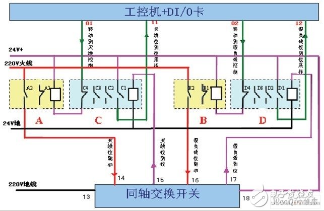
Figure 3 coaxial switch KT0-KT4 control and sampling principle
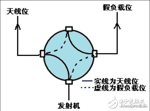
Figure 4 Schematic diagram of coaxial switch control
(1) Antenna in-position control and sampling
When the coaxial switch needs to turn to the antenna position, the industrial computer 01 will send a low level command, and send it to the lower end of the A relay line package through the C relay normally closed contact C4. After the A relay is powered, its normally open contact A2 is connected. Pass, the 220VAC control voltage is sent to the 14th end of the coaxial switch, the coaxial switch drive motor is powered up and starts to rotate (see Figure 4). When the coaxial switch is connected to the antenna, the coaxial switch 15 is sent out. The 24V antenna in-position information command is sent to the upper end of the C relay line package, the C relay is electrically connected, the C relay normally closed contact C4 is disconnected, the A relay line package is de-energized and immediately disconnected, and its normally open contact A2 is disconnected, the same The shaft switch drive motor is powered off. At the same time, the C relay normally open contact C1 is turned on, and the sampling signal of the +24V antenna in position is sent to the 11 end of the industrial computer DI/O card. At this point, the antenna in-position control is completed.
(2) dummy load in-position control and sampling
When the coaxial switch needs to turn to the dummy load position, the industrial computer 02 will send a low level command, and send it to the lower end of the B relay line package through the normally closed contact D4 of the D relay. After the B machine is powered, it normally opens. When the contact B2 is turned on, the 220VAC control voltage is sent to the 16th end of the coaxial switch, and the coaxial switch drive motor is powered up and starts to rotate (see Figure 4); when the coaxial switch is connected to the dummy load, the coaxial The switch 17 sends out the 24V dummy load in-position information command to the upper end of the D relay line package, the D relay is electrically connected, the D relay normally closed contact D4 is disconnected, the B relay line package is de-energized and immediately disconnected, and its normally open contact B2 is disconnected, the coaxial switch drive motor is powered off. At the same time, the D relay normally open contact D1 is turned on, and the sampling signal of the +24V dummy load is sent to the industrial computer DI/O card 12 terminal. At this point, the dummy load is in place control. carry out.
3.3 Site switch control and sampling circuit
3.3.1 Features
(1) Complete the control of the site switch.
(2) Implement hardware blocking function.
(3) Complete sampling of the position of the field switch.
3.3.2 Site switch control and sampling circuit principle
Fig. 5 is the control and sampling principle of the field exchange switch K1-K5, Fig. 6 is a schematic diagram of the field switch steering control, and Fig. 7 is a schematic diagram of the field switch through control. The drive motor inside the coaxial switch is 220VAC control.
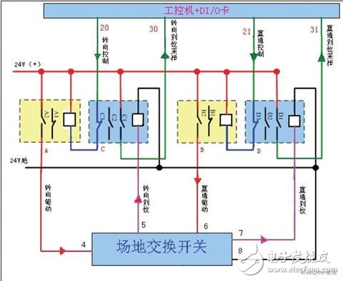
Figure 5 Field exchange switch K1-K5 control and sampling principle
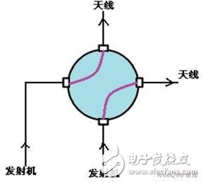
Figure 6 Schematic diagram of site switch steering control
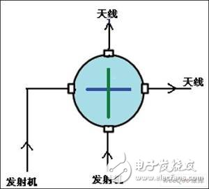
Figure 7 Schematic diagram of field switch through control
In Figure 5, the A relay is the field switch steering control relay, the C relay is the field switch steering in-situ sampling relay; the B relay is the field switch through control relay, and the D relay is the field switch through-in-sampling relay. The A, B, C, D relays and field switches are all 24VDC controlled.
(1) Steering drive control and sampling
When the field switch is in the through position and needs to be turned to the steering position, the industrial computer 20 sends a low level command, which is applied to the lower end of the A relay line package via the C relay normally closed contact C3. The normally open contact A2 is turned on, and the +24V control voltage is applied to the 4 terminals of the field exchange switch. The field switch drive motor is energized (see Figure 6 and Figure 7); when the field switch is turned from the through position to the steering position, The 5th end of the field exchange switch sends a 24V high level in-position information command and is added to the lower end of the C relay line package. The C relay is electrically connected, and its normally closed contact C3 is disconnected, causing the A relay to lose power and immediately disconnect. The A relay normally open contact A2 is disconnected, the field switch drive motor 24V is powered off, and the C relay normally open contact C1 is turned on, and the sampling signal of the 24V steering in position information is sent to the industrial computer DI/O card 30 end, the steering drive Control is complete.
(2) Through drive control and sampling
When the field switch is in the steering position and needs to be turned to the through position, the industrial computer 21 sends a low level command, which is applied to the lower end of the B relay line package via the D relay normally closed contact D3, after the B relay is powered, The normally open contact B2 is turned on, and the +24V control voltage is applied to the 6 terminals of the field exchange switch. The field switch drive motor is energized (see Figure 6 and Figure 7); when the field switch is turned from the steering position to the through position, The 7th end of the field exchange switch sends a 24V high level in-position information command and is added to the lower end of the D relay line package. The D relay is electrically connected, and its normally closed contact point D3 is disconnected, so that the B relay is de-energized and immediately disconnected. The B relay normally open contact B2 is disconnected, the field switch drive motor 24V is powered off, and the D relay normally open contact D1 is turned on, and the sampling signal of the 24V straight through position information is sent to the industrial computer DI/O card 31 end, the through drive Control is complete.
3.4 System security measures
(1) When the transmitter is pressurized, all its corresponding switches are not allowed to switch.
(2) The transmitter should be in the antenna position, and the antenna rotation is not in place; the transmitter should be in the dummy load position, and the transmitter cannot add high voltage when the dummy load is not in place.
(3) Since the blocking signal is not in place, the transmitter cannot add high voltage, so the system needs to judge whether each transmitter adds high voltage and judge whether the antenna or dummy load is turned into position.
(4) In order to ensure the high voltage safety of the transmitter, the system is designed with hardware and software blocking signals. The hardware blocking is given by the field switch and the coaxial switch. The software blocking signal is given by the system. When the high voltage condition is met, the software system gives The software lockout signal, when the software and hardware latching signals are satisfied, the system can add high voltage.
4 system softwareThe system software is designed to use the industrial control computer platform to complete the full function of the antenna control system. The operation is simple, practical, user-friendly and beautiful.
4.1 Software System Features
The functional structure diagram of the antenna automatic switching system is shown in Figure 8.
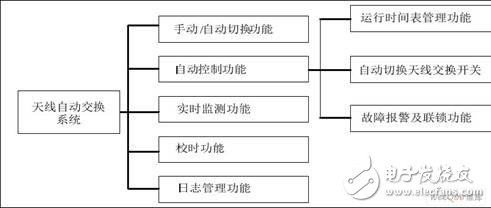
Figure 8 Functional structure diagram of the antenna automatic switching system
The functions of the antenna automatic switching system are as follows:
(1) The antenna automatic switching system realizes the automatic switching function of the antenna switching switch, and determines the antenna or dummy load that the transmitter needs to connect. The control of the antenna exchange switch includes three modes: manual operation, electric control and automatic control.
Manual operation: Mechanically switch antenna switching switches. (At this time, the system should not be in automatic mode, and there are corresponding measures to cut off the drive power, protect the equipment and personal safety, but the monitoring is still effective.) Electric control: on the control cabinet or control panel, through the artificial control of the electric switch, to achieve Switching of the antenna switch.
Automatic control: According to the operation schedule, the automatic control of the antenna exchange switch is realized by using the timing time pulse as the switching basis.
(2) The switching between the working modes of the automation system is selected on the screen of the upper computer, and after switching between the two, the operating state of the original antenna switching system must be maintained.
(3) During automatic operation, the system automatically receives the operation diagram issued by the remote equipment room and works according to the operation diagram.
(4) When running manually, the system administrator can directly modify the operation diagram of the monitoring system to complete the system control; the authority administrator can also edit the status of each control switch of the system and manually modify the data.
(5) Log management function: It can fully record the operation status and alarm information of the administrator, which is convenient for viewing the system operation.
4.2 Operation interface
(1) Welcome interface.
The welcome interface is shown in Figure 9.
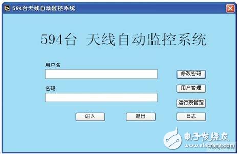
Figure 9 Welcome interface
Note: The login interface provides the user authentication function. Only users with administrator ID and password can use the system to ensure system security.
(2) Work mode selection
Note: The system provides two working modes, automatic and manual. Users can choose to use after logging in. The log is the system usage and fault record. Users can directly enter the view here.
(3) main interface (automatic operation)
The main interface of the antenna system automatic operation is shown in Figure 10.
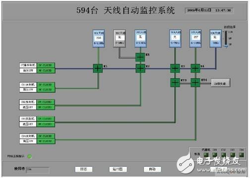
Figure 10 Antenna system automatic operation main interface
Description:
1 The basic functions of the system are automatic, manual, and log viewing functions, which are displayed in the form of buttons at the bottom of the main interface.
2 The green line in Figure 10 indicates that the broadcaster antenna path is on, and gray indicates that the antenna path is not on.
The blue line indicates that the docking antenna channel is turned on.
4.3 Basic flow chart of the software
The execution flow chart is the main software flow, and the system functions are completed (see Figure 11). The simple process of executing the process is as follows.
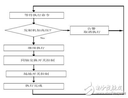
Figure 11 execution flow chart
After selecting the device (or switch) to be switched, click the “Execute†button to automatically switch between the antenna and the dummy load, the docking machine and the transmitter. The steps are as follows:
The first step: waiting for the "execute" command, if "execute"
The command arrives and the second step is executed.
Step 2: Check the status of the transmitter to see if it is connected to the relevant transmitter. If the transmitter connection is found, perform the third step. Otherwise, cancel the execution and issue an alarm.
The third step: executing the control program of the coaxial switching switch to realize automatic switching between the antenna and the dummy load.
Step 4: Execute the control program of the site switch to realize automatic switching between the transmitter and the docking machine.
5 ConclusionThe antenna control system has been in use for more than 2 years. In the daily operation of safe broadcast, the system works stably and is simple and flexible. It not only reduces the maintenance workload of the engine room attendant, but also reduces the failure rate and broadcasts the safety of the equipment room. A strong guarantee has been achieved.
Screen Protector,Uv Glue Screen Protector,Uv Tpu Film Screen Protector,Uv Curing Screen Protector
Shenzhen TUOLI Electronic Technology Co., Ltd. , https://www.szhydrogelprotector.com