
Recently, a STM32 user feedback in a forum, using the STM32F103 internal clock, the system clock is configured as a 64MHz microcontroller will not run, configured as a 36MHz program is normally properly, the frequency is slightly higher, it is easy to cause a crash. The code he posted is as follows:
Void RCC_Configuration(void)
{
RCC_DeInit();//Reset peripheral RCC registers to default values
RCC_HSICmd(ENABLE);//Enable HSI
While(RCC_GetFlagStatus(RCC_FLAG_HSIRDY) == RESET);//Wait for HSI to be successfully enabled
//FLASH_PrefetchBufferCmd(FLASH_PrefetchBuffer_Enable);
//FLASH_SetLatency(FLASH_Latency_2);
RCC_HCLKConfig(RCC_SYSCLK_Div1);
RCC_PCLK1Config(RCC_HCLK_Div2);
RCC_PCLK2Config(RCC_HCLK_Div1);
/ / Set the PLL clock source and multiplier
RCC_PLLConfig(RCC_PLLSource_HSI_Div2, RCC_PLLMul_16);
. . . . . .
Combined with his description of the problem and the code he posted, it can be roughly judged that it is because he blocked the exception caused by the parameter configuration of the instruction prefetch and the flash read wait delay. That is, the code marked in red above. 
Later, I clearly reminded him that after this point, he did not seem to respond in time, but also tossed a few times before the above configuration was opened, and the problem was finally solved.
In fact, this problem is often encountered, especially those who are based on the STM32 standard firmware library for development or self-programming is more likely to encounter this problem. The main reason is that they don't understand the function of the above two lines of code, which causes the relevant code in the library routine to be masked intentionally or unintentionally, regardless of configuration or incorrect configuration.
I will share this question again here and explain the above two lines of code briefly. I hope more people know about it and take a detour in this place.
This FLASH_PrefetchBufferCmd(); is used to enable or disable the flash instruction prefetch function.
The existing STM32 series are microprocessors based on the ARM cortexM core. The Harvard architecture adopts multi-stage pipeline, that is, the execution of one instruction is divided into several stages, such as fetching, decoding, and execution, so that the current instruction is fetched. After the operation is completed, the instruction fetching and decoding operations of the subsequent instructions can be started, and the program instructions are executed like a pipeline, which greatly improves the execution efficiency of the instructions.
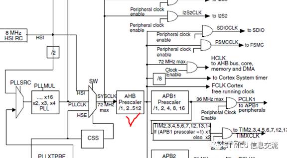
Specific to the STM32 series of single-chip microcomputers, this command prefetch function can be turned on or off by software configuration, generally configured to be on. It should be noted that after the chip is reset, some functions of the different series are turned on by default, and the default is off. For example, the flash command prefetch function of the STM32F1 series is turned on by default, of course you can also turn it off. Among them, the scenario that is explicitly required to be opened is when the AHB clock prescaler coefficient is not equal to one.
For example, the STM32F4 series, its instruction prefetch function is turned off by default after chip reset, you can open it yourself. However, the scene that is explicitly required to be turned off is when the power supply voltage of the chip is lower than 2.1V.
In fact, the pre-fetch function of STM32F4 is different from that of STM32F1. STM32F4, STM32F2, STM32L4, STM32F7 and other series chips use ST's patented ART storage accelerator [Adaptive real-time memory accelerator]. The accelerator uses the instruction prefetch queue and the branch jump cache technology to improve the execution speed of the Flash program code, so that the CPU can perfectly implement the wait for executing the flash program instruction even at its highest frequency.
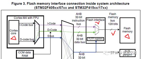
The above is a general introduction to the instruction prefetch function. Prefetching is mainly for the efficiency of instruction reading and execution. Please refer to the relevant technical manual for details. We know that the running speed of the CPU is adjustable, and it can be very fast. Usually, the FLASH interface controller is accessed by using the high-speed bus. The FLASH controller receives the instruction from the CPU and then reads the instruction or data of the corresponding address. The read speed of the Flash controller itself may be delayed compared to the high-speed request of the CPU, and the CPU is often required to wait for the delay. In order for the CPU to accurately and timely read the Flash data, we must correctly program the number of wait cycles (LATENCY) in the Flash Access Control Register (FLASH_ACR) according to the CPU clock frequency, the FLASH controller's own characteristics, and the device power supply, similar to the above. The second sentence of the code:
FLASH_SetLatency(FLASH_Latency_n);
The number of waiting cycles here varies depending on the STM32 series. For example, STM32F4 can be used:
Below is a table of LATENCY settings for some of the STM32F4 series product lines. It can be seen from the table that the setting of the LATENCY parameter is related to the clock and power supply voltage of the CPU. In addition, the prefetch function should be turned off when the power supply voltage is below 2.1V.
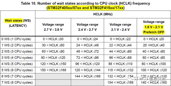
When setting the above waiting period parameters, just select the appropriate one. It is not difficult to understand that the setting is too big to affect the performance of the CPU, and it is too small to cause an abnormality.
Specifically back to the beginning of the case, it crashes, most likely because there is no reasonable configuration of the wait period parameter caused an exception, because it masks the two configuration code in the reference routine, that is, using its default function, for STM32F1, the instruction pre- The fetch function is enabled by default. The default value of the latency of the STM32F1 series chip is 0, no wait. In this case, it is not difficult to understand when he raises the clock to a certain degree.
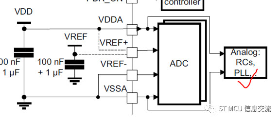
In addition, when his feedback clock was raised abnormally, I also reminded him to check the power supply of VDDA. I have encountered a situation where the PLL is not working properly because VDDA is not connected properly. We know that for the STM32 chip, the operating clock is increased, often with the aid of a phase-locked loop. The power supply of the PLL comes from VDDA. If the PLL is not powered normally, it is also a very hidden trouble. Once there was a customer who had tossed for a long time, and then he was willing to sink his heart to check the power supply of his "bad goods". As a result, he found a VDDA foot solder joint. There has been no problem with the low frequency of the chip. When the frequency is high, the abnormality is caused by the suspected chip quality problem.
Finally, give suggestions, if you are doing STM32 development, especially for novices, if you refer to the ST's official routines, some configurations should not be easily blocked or modified without understanding them. I encountered multiple initialization configuration codes or assertion code exceptions in the random blocking routine of this case, and I could not find the direction myself. In addition, as far as possible, use the ST official stm32cubeMx graphics configuration tool to do the basic configuration, through which to generate the initial configuration file, which is convenient and save a lot. Of course, even using the STM32CUBEMX configuration is not a panacea. For example: Someone used STM32F0 to develop products, and used CUBEMX to configure the initialization file. The clock selection was relatively low at the beginning of configuration. STM32CubeMx naturally configured the relevant parameters according to the clock of his choice. Later, he manually raised the clock in the user code, but did not know the corresponding adjustment parameters related to the FLASH read wait, but also the same situation as this case. So, if you can have more and deeper understanding of the principle, then it is better.
Paper Covered Flat Aluminium Wire
| About Paper Covered Flat Aluminium Wire |
Paper wrapped winding wire is made up of bare from oxygen free Copper Rod or electrical aluminum rod by drawing or extruding processing and wrapped by insulation materials.paper covered single wire , with insulation wrapping in the outside layer
As per Conductor Material:Copper , aluminum
As per Inner Conductor: Paper wrapped bare
Insulation thickness:Double paper covered (DPC) orTriple Paper Covered (TPC) ,According to Customer`s requirements
Packaging DetailsInner packing : Wooden bobbin
Outer packing : Wooden pallet and stretch film
Or according to our custormers' requirements

Production Scope
Conductor of Paper wrapped wire
Bare Wire Round Wire:Φ1.00 mm-Φ5.00 mm
Rectangular Wire thickness a:1.00 mm-5.60 mm
Width b:2.00 mm-16.00 mm
Conductor of Composite wires
Max wrapping layers once: 24 layers for Paper Covered Wire
4 layers per wire and 16 layers outside for composite wires
We could offer products of special requirements on conductor size, insulation layer thickness, or wire number of the composite.
Electrical Wire,Paper Covered Flat Aluminium Wire,Covered Magnet Aluminum Wire,Covered Magnet Aluminum Winding
HENAN HUAYANG ELECTRICAL TECHNOLOGY GROUP CO.,LTD , https://www.huaonwire.com