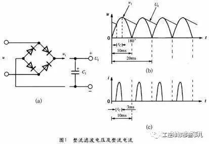
The 50Hz AC voltage is converted into a pulsating DC voltage u1 after full-wave rectification, and the DC high voltage U1 is obtained through the input filter capacitor. Ideally, the conduction angle of the rectifier bridge should be 180° (the conduction range is from 0° to 180°), but due to the effect of the filter capacitor C, only in the short time near the AC peak voltage, Only the input current flows through the rectifier bridge to charge C. The half cycle of the 50 Hz alternating current is 10 ms, the conduction time of the rectifier bridge is tC ≈ 3 ms, and the conduction angle is only 54° (the conduction range is 36° to 90°). Therefore, the rectifier bridge actually passes a narrow pulse current. The principle of the bridge rectifier filter circuit is shown in Fig. 1(a). The waveforms of the rectified filter voltage and the rectified current are shown in Figures l(b) and (c), respectively.
to sum up(1) The above characteristics of the rectifier bridge can be equivalent to a duty ratio corresponding to the input voltage frequency of approximately 30%. (2) The one-pass process of the rectifier diode can be regarded as a “strobe pulse†whose pulse repetition frequency is equal to the frequency of the AC grid (50 Hz).
(3) In order to reduce the conduction noise below 500 kHz in the switching power supply, sometimes two ordinary silicon rectifier tubes (such as 1N4007) and two fast recovery diodes (such as FR106) are used to form a rectifier bridge, and the reverse recovery time of trr06 is trr ≈ 250 ns.

The isolated switching power supply generally adopts a rectifier bridge composed of a rectifier tube, and can also directly select a finished rectifier bridge to complete bridge rectification. The full-wave bridge rectifier is referred to as a silicon rectifier bridge. It is a semiconductor device in which four silicon rectifier tubes are connected in a bridge form and then packaged in plastic. The utility model has the advantages of small volume, convenient use, good consistency of parameters of the rectifier tubes, and the like, and can be widely used for the rectifier circuit of the switching power supply. The silicon rectifier bridge has four terminals, two of which are an AC input terminal and a DC output terminal.
The maximum rectification current of the silicon rectifier bridge is divided into various specifications such as 0.5 to 40A, and the highest reverse working voltage is 50 to 1000V. The low-power silicon rectifier bridge can be soldered directly to the printed board. The large and medium-power silicon rectifier bridges must be screwed and a suitable heat sink must be installed.
The main parameters of the rectifier bridge are reverse peak voltage URM(V), forward voltage drop UF(V), average rectified current Id(A), forward peak surge current IFSM(A), maximum reverse leakage current IR (霡). The reverse breakdown voltage URR of the rectifier bridge should meet the following requirements:

For example, when the AC input voltage range is 85-132V, umax=132V, UBr=233.3V is calculated by equation (1), and the finished rectifier bridge with 400V can be selected. For a wide range of input AC voltage, umax = 265V, the same reason to obtain UBR = 468.4V, should be selected 600V withstand voltage rectifier bridge. It should be pointed out that if four silicon rectifier tubes are used to form the rectifier bridge, the withstand voltage of the rectifier tube should be further improved. The optional 1N4007 (1A/1000V), 1N5408 (3A/1000V) plastic sealed rectifiers are available. This is because the price of such pipes is low, and the safety and reliability of the rectifier bridge can be improved according to the principle that the withstand voltage value is "Ning Gao is not low".
Let the input RMS current be IRMS, and the rated rms current of the rectifier bridge be IBR, which should make IBR ≥ 2IRMS. The formula for calculating IRMS is as follows:

In the formula, PO is the output power of the switching power supply, η is the power supply efficiency, umin is the minimum value of the AC input voltage, and cosφ is the power factor of the switching power supply, allowing cosφ=0.5-0.7. Since the rectifier bridge actually passes not a sinusoidal current, but a narrow pulse current (see Figure 1), the average rectified current Id of the rectifier bridge is designed, for example, to design a 7.5V/2A (15W) switching power supply with an AC input voltage range of 85. ~265V, requires η=80%. Po=15W, η=80%, umin=85V, cosψ=0.7 were substituted into equation (2), IRMS=0.32A, and Id=0.65×IRMS=0.21A. The rectifier bridge of lA/600V is actually selected to leave a certain margin.
Our Professional 10W solar panel manufacturer is located in China. including Solar Module. PV Solar Module, Silicon PV Solar Module, 10W solar panel for global market.

10W solar panel, PV solar panel, Silicon PV solar module
Jiangxi Huayang New Energy Co.,Ltd , https://www.huayangenergy.com
