Frequency Division Multiplexing (FDM) divides the total bandwidth used for the transmission channel into several sub-bands (or sub-channels), and each sub-channel transmits one signal. Frequency division multiplexing requires that the total frequency width is greater than the sum of the frequency of each subchannel, and in order to ensure that the signals transmitted in each subchannel do not interfere with each other, an isolation band should be established between each subchannel, thus ensuring mutual signal mutual Does not interfere (one of the conditions). The frequency division multiplexing technology is characterized in that the signals transmitted by all subchannels work in parallel, and each transmission signal can be transmitted without considering the transmission delay, so the frequency division multiplexing technology has achieved a very wide application. In addition to frequency division multiplexing (FDM) in the conventional sense, frequency division multiplexing technology is also orthogonal frequency division multiplexing (OFDM).
Frequency division multiplexing and application examplesFirst, frequency division multiplexing
Concept: Multiplexing combines several messages that are independent of each other and transmits them in one channel.
Advantages: Improve channel utilization.
Multiplexing methods: frequency division multiplexing and time division multiplexing.
Frequency division multiplexing: It is to distinguish each channel signal by frequency, which is simply written as FDM, and is mostly used in analog communication systems.
Time-division multiplexing: It is a time-divisional signal, which is simply written as TDM and is mainly used in digital communication systems.
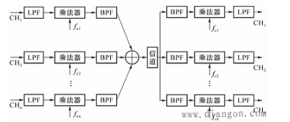
A block diagram of a frequency division multiplexing (SSB) system is shown in Figure 1.

Figure 1 Frequency division multiplexing system
At the transmitting end, the useful message signal is often not a strict band-limited signal, so each message at the transmitting end first passes through a low-pass filter and then modulated (eg, linearly modulated SSB). The low-pass signal is used to modulate different carriers, and the carrier frequencies of the respective carriers are appropriately selected so that the signals do not interfere with each other. The multiplexed signal is transmitted to the receiving end via the channel, and the signals of the respective frequency bands are first separated by a band pass filter, and then demodulated by a demodulator.
FIG. 2 is a schematic diagram showing the spectrum structure of a frequency division multiplexed signal using SSB as an example.

Figure 2 Spectrum structure of frequency division multiplexed signals
Among them, fe is a protective belt, which can avoid crosstalk between adjacent roads.
The total bandwidth of the n-side single-sideband signal shall be at a minimum equal to

The combined multiplexed signal can in principle be transmitted in the channel, but sometimes it can be modulated again in order to make better use of the transmission characteristics of the channel.
Second, application examples
1 FM stereo broadcast
The FM stereo broadcast system is an example of an FDM system.


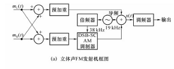
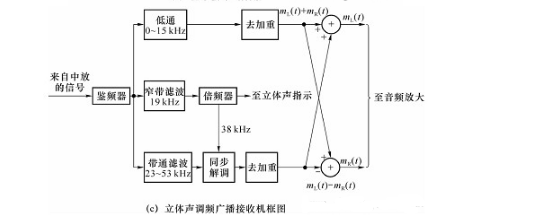
Figure 3 FM stereo broadcast transceiver block diagram
In FM FM stereo broadcast, the sound is spatially divided into two audio signals, one left channel signal and one right channel signal, all at a frequency of 0 to 15 kHz. Figure 3(a) shows a block diagram of an FM stereo broadcast transmitter. The baseband signals Mt(t) and Mr(t) are from the left and right microphones, adding and subtracting the two, adding the signal band to 0-15 kHz, and subtracting the signal [ML(t)-MR(T)] For DSB-SC AM modulation, the carrier frequency is 38 kHz, which is obtained after twice the frequency of the 19 kHz oscillator. A 19 kHz pilot is inserted into the composite signal spectrum for the purpose of facilitating coherent demodulation of the DSB-SC AM signal at the receiving end. The reason the pilot is 19 kHz instead of 38 kHz is that it is easier to separate from the composite signal in the receiver with this pilot. At the origin, the combined signal X(t) of the three is sent to the frequency modulator. Figure 3(b) shows the spectrum of X(t). It can be seen that the FM stereo broadcast is frequency division multiplexed by the sum of the left and right channels of the left and right channel signals. Figure 3(c) is a block diagram of an FM stereo receiver. The frequency discriminator converts the received FM signal into a frequency division multiplexed baseband signal X(t), which is obtained by a low-pass filter and a de-emphasis circuit of 0-15 kHz [ML(t)+MR (T)], the pilot is used to coherently demodulate the DSB-SC AM signal to obtain the [ML(t)-MR(T)] signal, and then the signals are added and subtracted respectively to recover ML(t And mr(t), which drive the speakers separately after the audio is amplified.
We are a professional screen protector manufacturer, providing one-stop product production solutions, providing exclusive OEM and ODM services. A wide range of products, including HD Clear Screen Protectors, Self-repair Screen Protectors, Anti-microbial Screen Protectors, Matte Screen Protectors, Privacy Screen Protectors and other series.
We are committed to the development, production and sales of hydrogel screen protectors. We strictly control the screen protector production process to ensure that each product meets industry standards. If you want to know more products, please click the product details to view.
Whether you are a group or an individual, we will do our best to provide you with the best service and the most accurate and comprehensive product information!
Universal Screen Protector, TPU Screen Protector, Hydrogel Protective Film, Mobile Phone Screen Protector, Hydrogel Screen Protector, TPU Protective Film
Shenzhen Jianjiantong Technology Co., Ltd. , https://www.jjthydrogelmachine.com
