
With the continuous expansion of the functions of the numerical control system, it is of great significance to use the functional parameters provided by the numerical control system to meet the mechanical requirements or to perfect the special design of the machine. In the following, the FANUC-Oi (M-type) numerical control system is taken as an example to introduce the reasonable application of the spindle gear shifting parameters.
In order to meet the cutting requirements of the user and give full play to the cutting power of the spindle motor, the spindle speed is generally divided into several gears, and the gear shifting is realized by the gearbox. Divided by the highest speed of the spindle motor, there are two forms of shifting the spindle. One is that the maximum speed of the spindle motor corresponding to the maximum speed of each gear of the spindle is the same. For example, our factory's XH756 horizontal machining center. The other is that the maximum speed of the spindle motor corresponding to the maximum speed of each gear of the spindle is different. This situation is mainly due to the fact that in the mechanical design, for special reasons, it needs to be electrically perfected. For example, our factory's XH716 vertical machining center.
The FANUC-0i CNC system takes these two situations into consideration and divides them into gear shifting modes A and B. Let's take the XH756 and XH716 of our factory as an example to introduce the clever application of gear shifting parameters.
1 gear shift mode A
As shown in Fig. 1, the maximum speed of the spindle motor corresponding to the three gear positions of the main shaft is the same. For example, our factory's XH756 horizontal machining center has a low-gear gear ratio of 11:108, a mid-range gear ratio of 11:36, and a high-end gear ratio of 11:12. The mechanical design requires a low-speed range of the spindle. It is O-458r/min, the mid-range speed range is 459-1375r/min, the high-end speed range is 1376-4125r/min, and the spindle motor's minimum speed is limited to 150r/min. When the spindle motor reference voltage is 1OV, the corresponding spindle motor speed is 6000r/min. It can be seen from the calculation that the maximum speed of the spindle motor of each gear position is the same, both 4500r/min. The parameters should be set as follows:
The parameter N0.3736 (the upper limit of the spindle speed, Vmax=4095×the spindle motor speed upper limit/the command motor voltage 10V spindle motor speed) is set to 4095×4500/6000=3071.
The parameter N0.3735 (spindle speed lower limit, Vmax=4095×spindle motor speed lower limit/spindle motor speed with command voltage 10V) is set to 4095×150/6000=102.
The parameter N0.3741 (spindle speed A corresponding to the command voltage 1OV, low gear) is set to 6000×11/108=611.
The parameter N0.3742 (the corresponding spindle speed B at the command voltage of 10 V, the mid-range) is set to 6000×11/12=1833.
The parameter N0.3743 (the corresponding spindle speed C at the command voltage of 10 V, the high speed) is set to 6000 × 11 / 12 = 5,500.
According to the above parameter setting, the speed range of the machine tool is reasonably covered, and it is automatically determined in the PMC program, and the gear position is selected reasonably. 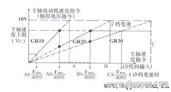
Figure 1
2 gear shift mode B
As shown in Fig. 2, the maximum speed of the spindle motor corresponding to the three gear positions of the main shaft is different.
For example, the spindle low gear ratio is 11:108, the spindle mid gear ratio is 260:1071, and the spindle high gear ratio is 169:
238, and the mechanical design requires the spindle low speed range is O-401r/min, the spindle midrange speed range is 402-1109r/min, and the spindle high speed range is 1110-3000r/min. When the spindle motor constant voltage is 10V, the corresponding spindle motor speed is 6000r/min, and the spindle motor speed lower limit is 150r/min. The calculation shows that the maximum speed of the motor used in the low-speed spindle is 401×108/11=3937r/min, the maximum speed of the motor used in the mid-range of the spindle is 1109×1071/260=4568r/min, and the maximum speed of the motor used in the spindle is 4000×238. /169=5633r/min, the maximum speed of the spindle motor corresponding to the three gear positions is different. At this time, the parameter N0.3736 is set to 4095×5633/6000=3844 (set at the highest gear of the spindle motor speed, this example is high-grade), and the parameter No.3735 is set to 4095×150/6000=102, the parameter NO.3741 is set to 6000×11/108=611, parameter N0.3742 is set to 6000×260/1071=1457, and parameter N0.3743 is set to 6000×169/238=4260.
Only after setting the above parameters, the actual spindle low speed will be 15-573r/min, the mid-range will be 574-1367r/min, and the high-end will be 1367-4000r/min. This does not meet the mechanical design requirements, which brings difficulties to automatic discrimination. To compensate for this deficiency, in gear shift mode B, parameters NO.3751 and NO.3752 can be used to limit the spindle speed.
The parameter N0.3751 (spindle motor speed at the switching point when the spindle is switched from the low gear to the neutral gear, Vmaxl=4095×the spindle motor speed upper limit at the low gear/the spindle motor speed with the command voltage of 10V) is set to 4095×3937/6000=2687.
The parameter N0.3752 (spindle motor speed when the spindle is switched from the mid-range to the high-end switching point, Vmaxh=4095×the spindle motor speed upper limit at the high-end speed/the spindle motor speed with the command voltage of 10V) is set to 4095×4568/6000=3118.
The setting of the parameters of this mode reasonably solves the trouble that the upper limit speed of each spindle motor is different for automatic shifting. 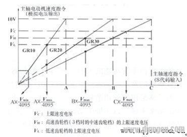
Figure 2
3 Conclusion Through the analysis of the above examples, we must fully combine the mechanical design features, combined with the requirements of the PMC program, rational use of the parameter functions provided by the CNC system, to achieve the perfect application of the control system functions.
SDL16 Plastic Pushbutton Switch
SDL16 series 16mm installation Pushbutton Switch refers to an electronic component that can open a circuit, interrupt current, or flow it to other circuits.We also called it for LA137-H series Pushbutton Switch,can be designed according to customer's needs.
The push button series are used in controlling circuit of AC voltage up to 660V/AC 50Hz~60Hz,and DC voltage below 400V.It is used for controlling signal and interlocking purposes.
They adopting the non-contacting accessories,self-locked contacting type,safe and reliable,and separate conveniently.Its shape is handsome, specially designed for industrial equipment, have firm fabrics, and have very good quality and very competitive prices. The switches have full and different kinds for different functions, like spring return type,self-locked type,with lamp type,mushroom head type,selector type,with key type and emergency stop type,etc.

SDL16 Series Pushbutton Switch,Push Button Light Switch,Mushroom Push Button Switch,Red Mushroom Head Pushbutton Switch
Ningbo Bond Industrial Electric Co., Ltd. , https://www.bondelectro.com