
In the general antenna production, since the impedance is related to the matching of the antenna, it is related to the standing wave of the antenna. Therefore, the standing wave is usually adjusted to be small, and the impedance is basically correct. In the engineering inspection of the antenna, it is usually only necessary to care about the standing wave ratio.
However, in the development and production of antennas, in order to clarify the direction of debugging and improve the speed and accuracy of debugging, it is necessary to test the impedance of the antenna.
The impedance is different from the standing wave. The standing wave is usually a scalar parameter, and it has nothing to do with the phase. The impedance is a vector parameter, which has a direct relationship with the phase. Measuring impedance is actually the phase of the reflection, and the accuracy of the phase measurement is related to the accuracy of the impedance.
However, it is often difficult to connect the feed point of the antenna directly to the instrument. Only the instrument can be connected to the other end of the feeder. The feeder has a length, and the signal passes through the feeder, and the phase changes. For example, a 10 MHz signal with a wavelength of 30 meters. This signal passes through a feeder with an electrical length of 7.5 meters and the phase is shifted by 90 degrees. During the test, the signal passes through the feeder twice and the phase moves 180 degrees. In layman's terms, if the antenna is capacitive, it is sensible. If the antenna is inductive, the measurement is capacitive.
When the length of the feeder is short, the phase shift will be less, and the error caused will be reduced. However, short-wave antennas are generally erected and the feeders are always long. Even a 1 meter long feeder will cause a total phase shift of around 30 degrees at 10 MHz, and the test results are still completely wrong. Can I use a feed line with a length of one-half wavelength to make the phase just turn 360 degrees, thus eliminating the impact? In principle, of course, there is no problem, but preparing one-half of the feeder is a nuisance. Secondly, since the wavelength of each frequency is different, only a specific frequency can be rotated 360 degrees, which means that the test result can only be specific. The frequency is valid.
When testing the impedance of an antenna, you must think of other methods. The following is an example:
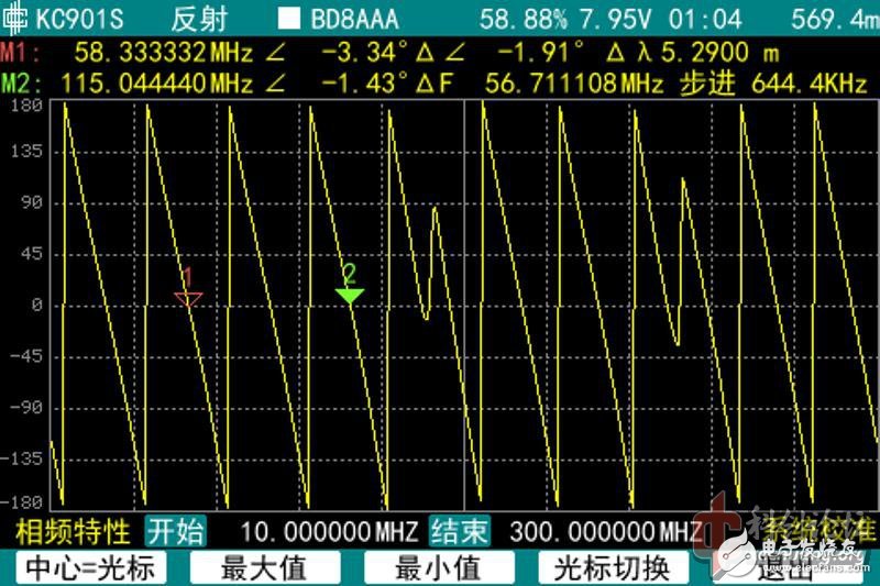
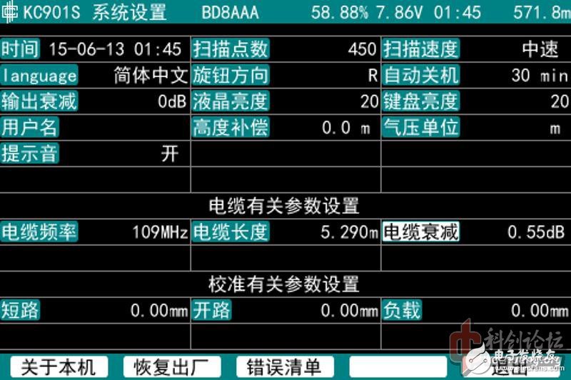
First look at the phase and measure the electrical length of the feeder. If it is better to remove the feeder from the antenna, if it can't be removed, look for the frequency away from the antenna resonance point. The electrical length of the feeder is about 5.29 meters.
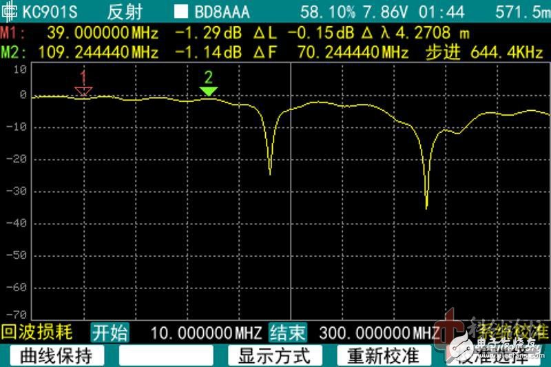
If the requirements are strict, the loss of the feeder can be measured again. If you can use the dual port method is best, if it is not convenient, you can also use a single port, take the smaller loss, here measured about 1.1dB @ 109MHz.
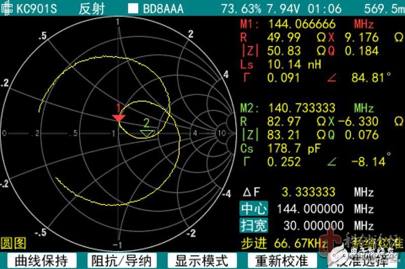
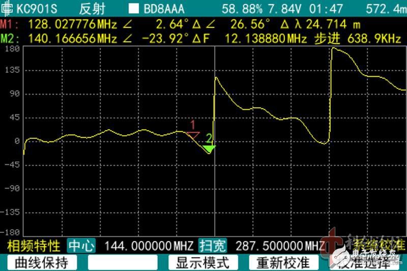
Then we first look at the assumption that the effect of the feeder is not eliminated, and what results are obtained (the antenna is 144MHz)
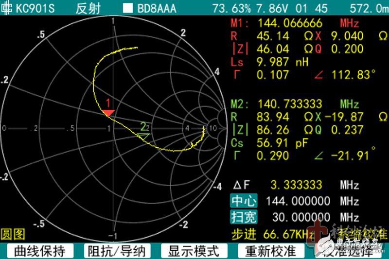
This is a circle chart
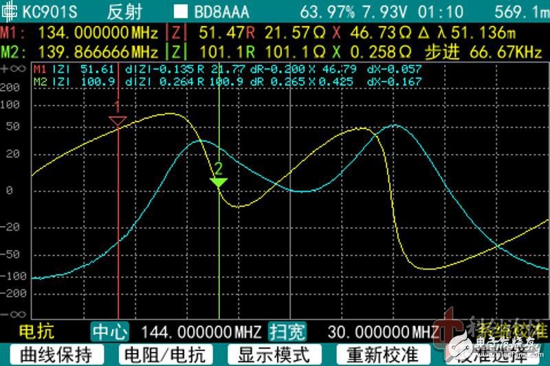
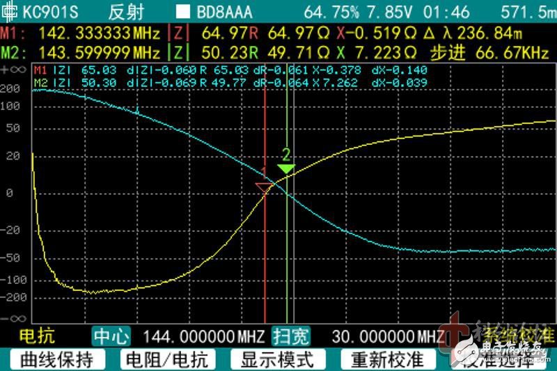
This is the impedance
If you don't keep in mind the principle of "no feeders are not allowed", it is easy to be deceived by the above erroneous data.
Now let's eliminate the feeder. First tell the instrument the electrical length and loss of the feeder (one-half of the return loss)
Then get the basic correct measurement results.
This is the phase after the correction
This is the round chart after the correction.
This is the corrected impedance
The difference is great! If the antenna is debugged according to the result of no correction, it is possible to smash it.
By using the feeder compensation method to eliminate the error, basic and accurate results can be obtained, which can meet the general needs. If you want to accurately eliminate the influence of the feeder, you can calibrate at the end of the feeder. The regular vector antenna analyzer has calibration function.
The reason why this article does not use the calibration method to eliminate the feeder is to more intuitively reflect the influence of the feeder on the phase and the principle of elimination. When making an antenna, it should in principle be measured at the feed point of the antenna. In the past, this kind of measurement was very difficult. Now you don't have to really test at the feed point, you can calculate the data when measuring at the feed point. If a balun or impedance transformer is present in front of the antenna, it can also be measured on the port of the balun or impedance transformer, but the best way is to connect the instrument to the front of the converter and then calibrate it behind the converter. In the case of correct calibration, the short-circuit or open-circuit reflection phase-frequency characteristics should be a relatively stable angle. At this point, the antenna feed point is connected to the antenna to reflect the real situation.
Professional DC Charging Station manufacturer is located in China, including DC Ev Charger,DC Charging Pile,DC Fast Charger, etc.
DC Charging Station,DC Ev Charger,DC Charging Pile,DC Fast Charging
Shenzhen Hongjiali New Energy Co., Ltd. , https://www.hjlcharger.com