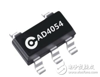
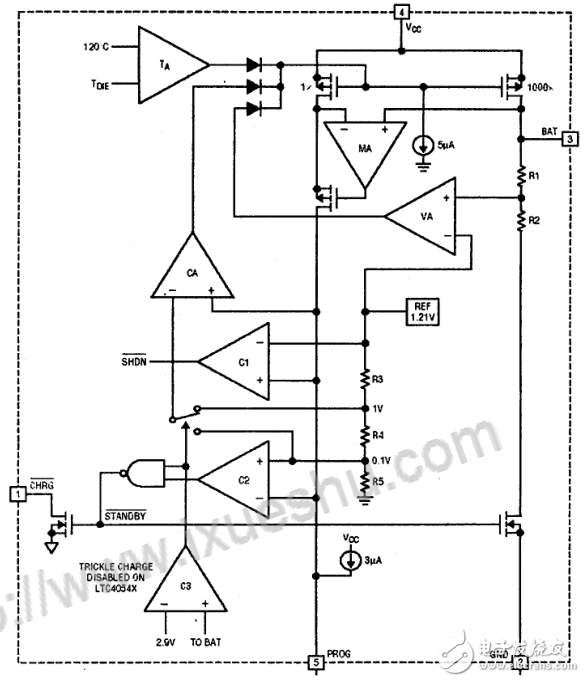
The LTC4054 is a lithium battery charging chip from Linear Technology, a monolithic integrated chip designed to charge a single-cell lithium battery. The charger designed with the LTC4054 requires only a few components and is very compact. LTCA054 can charge the battery with high current without special heat sink, and it can take power from USB port. It is very suitable for peripheral devices such as MP3, PDA, digital recorder, etc. .

The TC4054 is a single-cell lithium battery charger that uses a constant current/constant voltage charging algorithm. It provides up to 800mA of charging current (using a better heat sink PCB) with a final charging voltage accuracy of ±1%. The LTCA054 has a built-in P-channel MOSFET power tube and temperature regulation circuit, eliminating the need for an isolation diode and an external current sense resistor, so the basic charger circuit requires only three external components. In addition, the LTC4054 can also take power from the USB port.

Ordinary charging cycle
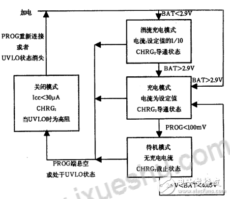
The charge cycle begins when the Vcc supply exceeds the UVLO-limited voltage and a 1% precision resistor is connected between PROG and GND. If the voltage at the BAT pin is lower than 2.9V, the charger enters the trickle charge mode. In this mode, the LTCA-054 charges with approximately 1/10 of the charge current setting value, causing the terminal voltage of the battery to rise to a large value. Safe voltage for current charging (Note: The LTC4054X does not have this trickle charge function). When the voltage at the BAT terminal rises above 2.9V, the charger enters the constant current charging mode to charge the battery with the programmed current. When the voltage at the BAT terminal is close to the final charging voltage of 4.2V, the LTC4054 enters the constant voltage charging mode, and the charging current begins to decrease. The charging cycle ends when the charging current drops to 1/10 of the charging current setting.
Set the charging current
The charging current is set by a resistor connected between PROG and GND. The charging current of the battery is 1000 times the output current of the PROG terminal. This resistance and charging current are calculated by the following equation: Rprog = 1000V / Ichrg, Ichrg = 1000V / Rprog, the current output to the battery can be calculated by monitoring the voltage of PROG at any time by: Ibat = (Vprog / Rprog) *1000.
Termination of charging
The charging cycle is terminated when the charging current drops to 1/10 of the set value. The built-in comparator monitors that the LTCA054 enters standby when the PROG terminal voltage is below 100mY (any factor that causes the PROG terminal voltage to be above 100mY will prevent the LTCA054 from aborting the charge cycle). In the standby state, LTCA054 suspends the supply of charging current to the battery, at which time the input supply current drops to 200μA. When the battery terminal voltage is lower than 4.05V, the charger will automatically start recharging. To manually restart the charge cycle, you must power cycle and then power cycle or turn off the charger and temporarily disconnect the PROG pin.
Charging status indication
The charge state output has three different states: a high current state (10 mA), a low current state (20 μA), and a high resistance state. The first indicates that the LTC4054 is in the charge cycle state, and once the charge cycle is terminated, the pin state is determined by UVLO. The second indication that Kc is not in the UVLO state, the LTC4054 is ready for charging. The third indication is that the LTC4054 is in the UVLO state, and the Vcc supply is insufficient, which is less than 100mV of the BAT terminal voltage. The microprocessor can distinguish between these three states.
Temperature limit
The built-in temperature feedback loop reduces the charge current setting if the die temperature rises to approximately 120 °C. This feature protects the LTC4054 from overheating, allowing the user to not damage the LTCA054 chip regardless of the thermal dissipation capability of a given board. In the case of ensuring that the charger can automatically reduce the charging current in the worst case, the charging current can be set at a typical ambient temperature (not the worst case).
Undervoltage lockout (UVLO)
A built-in undervoltage lockout circuit monitors the input supply voltage, turning the charger off until Vcc rises above the UVLO voltage. The UVLO circuit has a 200mV hysteresis characteristic. In addition, to prevent reverse current of the MOSFET power tube, the UVLO circuit forces the charger to be off when the Vcc voltage is lower than 30mY of the battery voltage. When the UVLO comparator is inverted, the charger will not cancel the shutdown state unless Vcc rises. More than 100mV of battery voltage.
Manually close
At any point in the charge cycle, the LTC4054 is turned off by disconnecting the resistor Rprog of the PROG pin, allowing the battery to consume less than 2μA and the supply current to be less than 50μA. The connection of the recovery resistor RPROG will start a new charging cycle.
Automatic refill
Once the charge cycle is terminated, the LTCA054 continues to monitor the voltage at the BAT terminal. When the battery voltage drops to 4.05V (which is equivalent to approximately 80% to 90% of the capacity of the battery), the battery will be recharged, which ensures that the battery is fully charged. Eliminate the need to restart the entire charge cycle. The CHRG terminal is in an on state during recharging. The charging process is shown in the figure.

Icom mobile radio,Hytera Digital Mobile Radio,Radio Hytera Md785,Hytera Dmr Mobile Radio
Guangzhou Etmy Technology Co., Ltd. , https://www.digitaltalkie.com
