
Advanced Current Mode (ACM) with internal compensation is a new control topology developed by TI that supports true fixed frequency modulation and is synchronized with internal compensation. Fundamentally, this product is similar to the Simulated Peak Current Mode (PCM) control, which maintains a range of input voltage and output voltage stability for fast transient response. The difference between ACM is that it is a gradual, peak current mode control scheme that can be internally ramped to achieve true frequency without external compensation. ACM also has good anti-interference performance for power stage variables (inductors and capacitors), but here I will introduce the advantages of ACM in more detail.
Why choose internal compensation ACM?
Some control topologies support true or pseudo-fixed frequencies without an external compensation network. However, there are some disadvantages in use.
Most existing true-frequency/no-compensation converters use traditional peak current mode to transfer compensation components from the outside of the circuit package to the inside of the circuit, along with a designed and optimized internal compensator for various applications. . Because internal compensation needs to cover a wide range of voltage regulation, internal loop and slope compensation are difficult to optimize if fast transient response is to be achieved. Loop bandwidth must also be limited to meet a wide range of practical applications. In general, you will see a very slow transient response, especially when a large load current changes stepwise.
In addition to this, there is a control topology with a constant on-time modulator. Like TI's D-CAPTM/D-CAP3TM control mode, such a control topology maintains pseudo-frequency without external compensation. For some VINs and VOUTs, the on-time is constant, and during load transients, the switching frequency is varied to achieve good transient performance. However, such frequency changes can also cause electromagnetic interference problems, especially for telecommunications applications sensitive to electromagnetic interference. ACM with internal compensation solves the problems caused by fixed frequency and constant on-time control.
The simplified version of the ACM buck configuration shown in Figure 1 below provides feedback voltage information from the output stage to the internal integrator without the need for an external compensation network.
Figure 1. Simplified ACM buck structure
The advantages of a simple control structure:
l The output voltage feedback loop has good performance and is easy to operate. There is no need to compensate the network, only RS1 and RS2 can be used as a resistor divider to sense Vout, and the sensed Vout information will be sent back to the control loop via VFB.
l Because PID (proportional-integral-derivative) or PI (proportional-integral) compensation does not rely on external components, designers can use complex compensation designs to make them more convenient.
l Eliminating the use of external compensation components also saves component count and valuable printed circuit board space.
Internally compensated ACM control overview
The overall ACM control loop block diagram is shown in Figure 2. The ACM contains voltage loops, ramp loops, comparators, current feedback, and pulse width modulation (PWM) logic.
Figure 2. Internal components controlled by ACM
Each component function:
The voltage loop senses and processes the VFB error signal.
The ramp circuit generates a ramp voltage based on the VIN and PWM signals. The optimized slope compensation value is only half of the falling slope ramp voltage.
The loop comparator can generate an input signal and terminate the PWM cycle when the positive input total value is equal to the negative input total value.
Current feedback also uses DC information to optimize the Q factor of the loop.
The PWM logic generates a PWM signal based on the output of the clock and loop comparators.
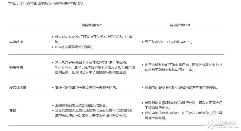
Comparison of traditional PCM and internal compensation ACM
Table 1 shows a comparison of the traditional peak current mode and the internal compensation ACM:
in conclusion
The ACM control with internal compensation is a gradual, peak current mode control scheme that eliminates the need for external compensation to create a true internal frequency ramp. By independently optimizing the DC and AC sections of the voltage and ramp circuits, ACM can provide better transient response than traditional peak current modes. This control mode provides an optimized solution for applications with predictable frequencies that do not require external compensation. TI's high-performance TPS543B20 and TPS543C20 step-down converters include a new internal compensation ACM control. The converter supports 25/40A, has stack capability (TPS543C20 only), and includes easy internal compensation, fixed frequency with low EMI noise and full differential sensing for optimum VOUT set point accuracy.
The utility model relates to a medical atomization treatment and humidifying device belonging to the technical field of medical equipment and household appliances.
Professional Medical Atomization manufacturer is located in China, including Medical Vape,Dose Control Vape Pen,Supersonic Wave Vape, etc.
Medical Atomization,Medical Vape,Dose Control Vape Pen,Supersonic Wave Vape
Shenzhen MASON VAP Technology Co., Ltd. , https://www.e-cigarettefactory.com