
1. After the downloaded rt-thread-2.0.1 is decompressed, the file list shown in the following figure is obtained.
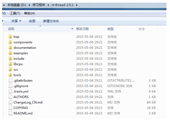
The stm32f40x folder can be found in the bsp directory. This folder contains the library functions. All other chip platform folders are deleted. Under libcpu, you only need to keep the common and cortex-m4 in the arm folder. All other files are also deleted. There are other supporting documents, such as: documentaTIon, examples, tools, etc. We also delete all, after processing these, a clean RTT is ready.
2. Although RT-thread classifies files well, it is better to organize the entire project according to your own project habits. The entire software project is divided into four parts: app, bsp, mdk, rt-thread-2.0.1. As shown below.
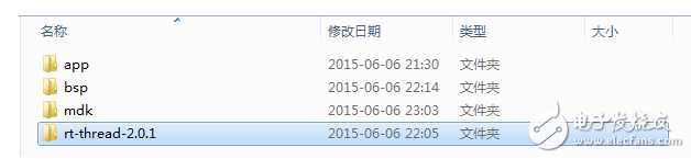
App: application layer, storing application files written by the project during development
Bsp: driver layer, which mainly includes the underlying driver of RT-thread in the stm32f40x platform (applicaTIons, drivers, libraries_1.5.0), and the peripheral driver used by the project.
Mdk: store the related project files of keil mdk5.15
Rt-thread-2.0.1: system layer, storing components (system components), include (system kernel headers), libcpu (chip migration), and src (system kernel source files) in rt-thread-2.0.1
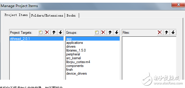
3. After the keil mdk5.15 is installed, create a new project file and save it in the mdk folder. Add source files according to the project file classification, as shown in the following figure.
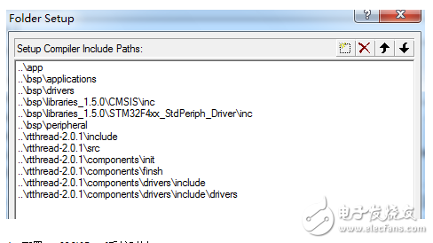
Then add the header file directory to the project, as shown in the following figure.
4, configure the stm32f407vgt6 system clock
(1) Select #define STM32F40_41xxx and #define USE_STDPERIPH_DRIVER in the stm32f4xx.h file;
(2) Modify the default system external crystal clock in the stm32f4xx.h file #define HSE_VALUE ((uint32_t)8000000)
(3) Modify the value of the PLL_M, PLL_N (PLL_P=2) of the device selected in the system_stm32f4xx.c file for the system clock. For the stm32f407xx, the system clock is 168MHZ. Generally, only PLL_M and PLL_N need to be modified.
#if defined(STM32F40_41xxx) || defined(STM32F427_437xx) || defined(STM32F429_439xx) || defined(STM32F401xx)
/* PLL_VCO = (HSE_VALUE or HSI_VALUE / PLL_M) * PLL_N */
#define PLL_M 8
. . . . . .
#if defined(STM32F40_41xxx) || defined(STM32F427_437xx) || defined(STM32F429_439xx) || defined(STM32F446xx)
#define PLL_N 336
/* SYSCLK = PLL_VCO / PLL_P */
(4) Using the FPU of stm32f40_41xxx, it is necessary to add related statements at the beginning of the SystemInit function, and FauaTIng Point Hardware selects “Use Single Precision†in the keil project configuration.
(#define __FPU_PRESENT is set by default in stm32f4xx.h, and __FPU_USED == 1 is set by default in core_cm4.h).
/* FPU setTIngs ---------------------------------------------- --------------
* If no this settings, it maybe enter HardFault_Handler() interrupt when mdk complier chose “Use Single Precision†to use FPU instruction. */
#if (__FPU_PRESENT == 1) && (__FPU_USED == 1)
SCB-"CPACR |= ((3UL "10*2"|(3UL "11*2)); /* set CP10 and CP11 Full Access */
#endif
(5) Comment out the HardFault_Handler, PendSV_Handler, and SysTick_Handler interrupt entry functions in stm32f4xx_it.h and stm32f4xx_it.c.
HardFault_Handler and PendSV_Handler implement RT-thread system exception handling and thread switching respectively in the context_rvds.S file;
SysTick_Handler implements RT-thread system tick count in board.c.
(6) Determine the stm32f407 SRAM size and the SRAM end address in board.h. The stm32f407vg has a total of 192K of SRAM (only 128k can be accessed with a starting address of 0x20000000).
// "o" ​​Internal SRAM memory size[Kbytes] "8-64"
// "i"Default: 64
#define STM32_SRAM_SIZE 128
#define STM32_SRAM_END (0x20000000 + STM32_SRAM_SIZE * 1024)
5, if you need to enable finsh components and component initialization functions in the project, in order to ensure that the user to write their own functions will not be optimized by the keil compiler, you need to modify the MDK settings, as follows:

Under the Linker-> Misc controls tab, type the command "--keep __fsym_* --keep __vsym_* --keep __rt_init_*", which will hold the function that was not called by the body of the function. This allows you to run functions that have not been called while debugging with the finsh component.
6, modify the system configuration file rtconfig.h related system parameters, as shown below for the system basic configuration:
/* RT-Thread config file */
#ifndef __RTTHREAD_CFG_H__
#define __RTTHREAD_CFG_H__
/* RT_NAME_MAX*/// specifies the maximum length of the system kernel object name (such as threads, semaphores, mutexes, events, etc.), and the excess part will be automatically cut off
#define RT_NAME_MAX 8
/* RT_ALIGN_SIZE*/// Most systems require address alignment in the stack space (for example, the ARM architecture requires 4-byte address alignment). The system default setting is 4-byte alignment, which can be set to 8-byte alignment.
#define RT_ALIGN_SIZE 8
/* PRIORITY_MAX *///RT-thread supports up to 256 thread priorities (0~255,0 is the highest priority, 255 is allocated to idle threads). In the case of limited resources, it is generally set to support 8 or 32 priorities.
#define RT_THREAD_PRIORITY_MAX 32
/* Tick per Second */// The number of ticks per second for the system clock. 1000 means that rt_tick increases by 1000 within 1 s, ie, the clock tick is 1 ms; if it is set to 100, rt_tick increases by 1 every 10 ms and the clock tick is 10 ms.
#define RT_TICK_PER_SECOND 1000
/* Using Hook *///Use the hook (callback) function
#define RT_USING_HOOK
/* Idle thread stack */// Set the idle thread stack size to 1024 bytes
#define IDLE_THREAD_STACK_SIZE 1024
/* Using Software Timer */// Software timer thread mode (this mode is not used here). The RT-thread system clock is generally defaulted to the hardware timer interrupt mode of the selected chip platform
// #define RT_USING_TIMER_SOFT
#define RT_TIMER_THREAD_PRIO 4
#define RT_TIMER_THREAD_STACK_SIZE 512
/* SECTION: RT_DEBUG */// thread debugging and component initialization module
/* Thread Debug */
#define RT_DEBUG
#define RT_DEBUG_INIT 1 //Component initialization debug mode (this mode is not necessary if you do not need to print initialization information to PC via serial console)
#define RT_USING_COMPONENTS_INIT //Enable component initialization
#define RT_USING_OVERFLOW_CHECK //Enable thread stack overflow checking
/* SECTION: IPC *///interprocess communication kernel objects: semaphores, mutexes, events, mailboxes, message queues
/* Using Semaphore*/
#define RT_USING_SEMAPHORE
/* Using Mutex */
#define RT_USING_MUTEX
/* Using Event */
#define RT_USING_EVENT
/* Using MailBox */
#define RT_USING_MAILBOX
/* Using Message Queue */
#define RT_USING_MESSAGEQUEUE
/* SECTION: Memory Management *///RT-thread system memory management: use static memory pool, dynamic heap (small memory management algorithm)
/* Using Memory Pool Management*/
#define RT_USING_MEMPOOL/* Using Dynamic Heap Management */
#define RT_USING_HEAP
/* Using Small MM */
#define RT_USING_SMALL_MEM
/* SECTION: Device System *///I/O device management of system components: Enable I/O devices and inter-device communication
/* Using Device System */
#define RT_USING_DEVICE //Open the corresponding macro definition in rtconfig.h according to the macro definition of all devices in rtdevice.h, such as the following 4 types of devices
/* Using GPIO pin framework *///GPIO devices
#define RT_USING_PIN
/* Using serial framework */ //Serial device
#define RT_USING_SERIAL
/* Using SPI framework */ //SPI device
#define RT_USING_SPI
/* Using I2C framework */ //I2C device
#define RT_USING_I2C
#define RT_USING_I2C_BITOPS
/* SECTION: Console options */// System Console: Enable the console and set the console device to cache 256 bytes. If you use rt_kprintf to print information to the PC, you must enable the console and set up a console device (such as a serial port).
#define RT_USING_CONSOLE
/* the buffer size of console*/
#define RT_CONSOLEBUF_SIZE 256
/* SECTION: finsh, a C-Express shell *///finsh component (finsh is the command line shell of the RT-thread system, providing a set of interfaces for the user at the command line, mainly for debugging, viewing system information)
#define RT_USING_FINSH
/* Using symbol table */
#define FINSH_USING_SYMTAB
#define FINSH_USING_DESCRIPTION
/* SECTION: device filesystem *///File System
/* Using Device file system */ //No file system is used in the project
// #define RT_USING_DFS
/* the max number of mounted filesystem */
#define DFS_FILESYSTEMS_MAX 2
/* the max number of opened files */
#define DFS_FD_MAX 4
/* Using ELM FATFS *///ELM FATFS file system (not used in project)
// #define RT_USING_DFS_ELMFAT
#define RT_DFS_ELM_WORD_ACCESS
/* Reentrancy (thread safe) of the FatFs module. */
#define RT_DFS_ELM_REENTRANT
/* Number of volumes (logical drives) to be used. Each volumes maybe include one primaly partition and some logical partitions.
* If _MULTI_PARTITION is defined to 0 in ffconf.h, each volume can mount only first primaly partition */
#define RT_DFS_ELM_DRIVES 2
/* Long File Name(LFN) with dynamic LFN working buffer on the heap. */
#define RT_DFS_ELM_USE_LFN 3
#define RT_DFS_ELM_MAX_LFN 255
/* The _CODE_PAGE specifies the OEM code page to be used on the target system. 936-Simplified Chinese GBK (DBCS, OEM, Windows); 437 - US (OEM) */
#define RT_DFS_ELM_CODE_PAGE 437
/* Maximum sector size to be handled. It must be the real size(byte) of spiflash sectors. */
#define RT_DFS_ELM_MAX_SECTOR_SIZE 4096
/* Using ROM file system *///ROMFS file system (not used in project)
// #define RT_USING_DFS_ROMFS
/* SECTION: lwip, a lighwight TCP/IP protocol stack */// Lightweight TCP/IP stack (not used in the project)
// #define RT_USING_LWIP
/* LwIP uses RT-Thread Memory Management */
#define RT_LWIP_USING_RT_MEM
/* Enable ICMP protocol*/
#define RT_LWIP_ICMP
/* Enable UDP protocol*/
#define RT_LWIP_UDP
/* Enable TCP protocol*/
#define RT_LWIP_TCP
/* Enable DNS */
#define RT_LWIP_DNS
/* the number of simulatenously active TCP connections*/
#define RT_LWIP_TCP_PCB_NUM 5
/* ip address of target*/
#define RT_LWIP_IPADDR0 192
#define RT_LWIP_IPADDR1 168
#define RT_LWIP_IPADDR2 1
#define RT_LWIP_IPADDR3 201
/* gateway address of target*/
#define RT_LWIP_GWADDR0 192
#define RT_LWIP_GWADDR1 168
#define RT_LWIP_GWADDR2 1
#define RT_LWIP_GWADDR3 1
/* mask address of target*/
#define RT_LWIP_MSKADDR0 255
#define RT_LWIP_MSKADDR1 255
#define RT_LWIP_MSKADDR2 255
#define RT_LWIP_MSKADDR3 0
/* tcp thread options */
#define RT_LWIP_TCPTHREAD_PRIORITY 12
#define RT_LWIP_TCPTHREAD_MBOX_SIZE 4
#define RT_LWIP_TCPTHREAD_STACKSIZE 1024
/* ethernet if thread options */
#define RT_LWIP_ETHTHREAD_PRIORITY 15
#define RT_LWIP_ETHTHREAD_MBOX_SIZE 4
#define RT_LWIP_ETHTHREAD_STACKSIZE 512
/* TCP sender buffer space */
#define RT_LWIP_TCP_SND_BUF 8192
/* TCP receive window. */
#define RT_LWIP_TCP_WND 8192
#define CHECKSUM_CHECK_TCP 0
#define CHECKSUM_CHECK_IP 0
#define CHECKSUM_CHECK_UDP 0
#define CHECKSUM_GEN_TCP 0
#define CHECKSUM_GEN_IP 0
#define CHECKSUM_GEN_UDP 0
/* RT_GDB_STUB *///GDB debugging tool (not used in project)
//#define RT_USING_GDB
#endif
High efficient charging speed for Samsung laptop, stable current outlet can offer power for the laptop at the same time charge the laptop battery. The best choice for your replacement adapter. We can meet your specific requirement of the products, like label design. The plug type is US/UK/AU/EU. The material of this product is PC+ABS. All condition of our product is 100% brand new.
Our products built with input/output overvoltage protection, input/output overcurrent protection, over temperature protection, over power protection and short circuit protection. You can send more details of this product, so that we can offer best service to you!
Samsung Adapter,Charger For Samsung,Power Supply For Samsung,Laptop Charger For Samsung
Shenzhen Waweis Technology Co., Ltd. , https://www.waweis.com